CHV180 series frequency inverter special for elevator Extension card
.81.
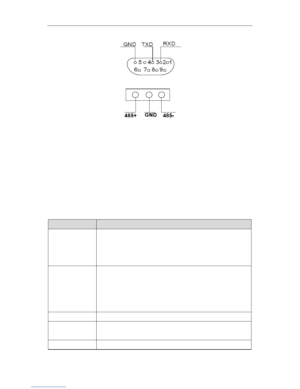
There are 2 groups of wiring terminals.
Figure 7.3 DB9: Bus-connector wiring terminal (RS232)
Figure 7.4 RS485 wiring terminal
7.1.5 Wiring precautions
Please install the card when the inverter is disconnected completely.
Please connect the communication card with the slot of the control board with proper
techniques.
Tighten the communication card with screws.
In order to avoid the external interference of the communication signal, please select
twisted pairs and avoid the parallel route of the drive power.
Please select shield cables as the communication connection.
7.2 Description of I/O extension card
7.2.1 Terminals instruction of IO extension card
Terminal name
PW and COM.
Input voltage range: 9~30V
Input impedance: 3.3kΩ
HDI2
High speed pulse or open collector input, optical coupling
input terminal with PW and COM.
Pulse input frequency: 0~50kHz
Input voltage: 9~30V
Input impedance:1.1kΩ
COM Common ground terminal for +24V or external power supply
AI3
Analog input, voltage range: -10V~10V
Input impedance:10kΩ
AI4 Analog input: 0~10V/0~20mA selected by J1
 Loading...