User manual of EC160 elevator intelligent integrated machine Installation and wiring
30
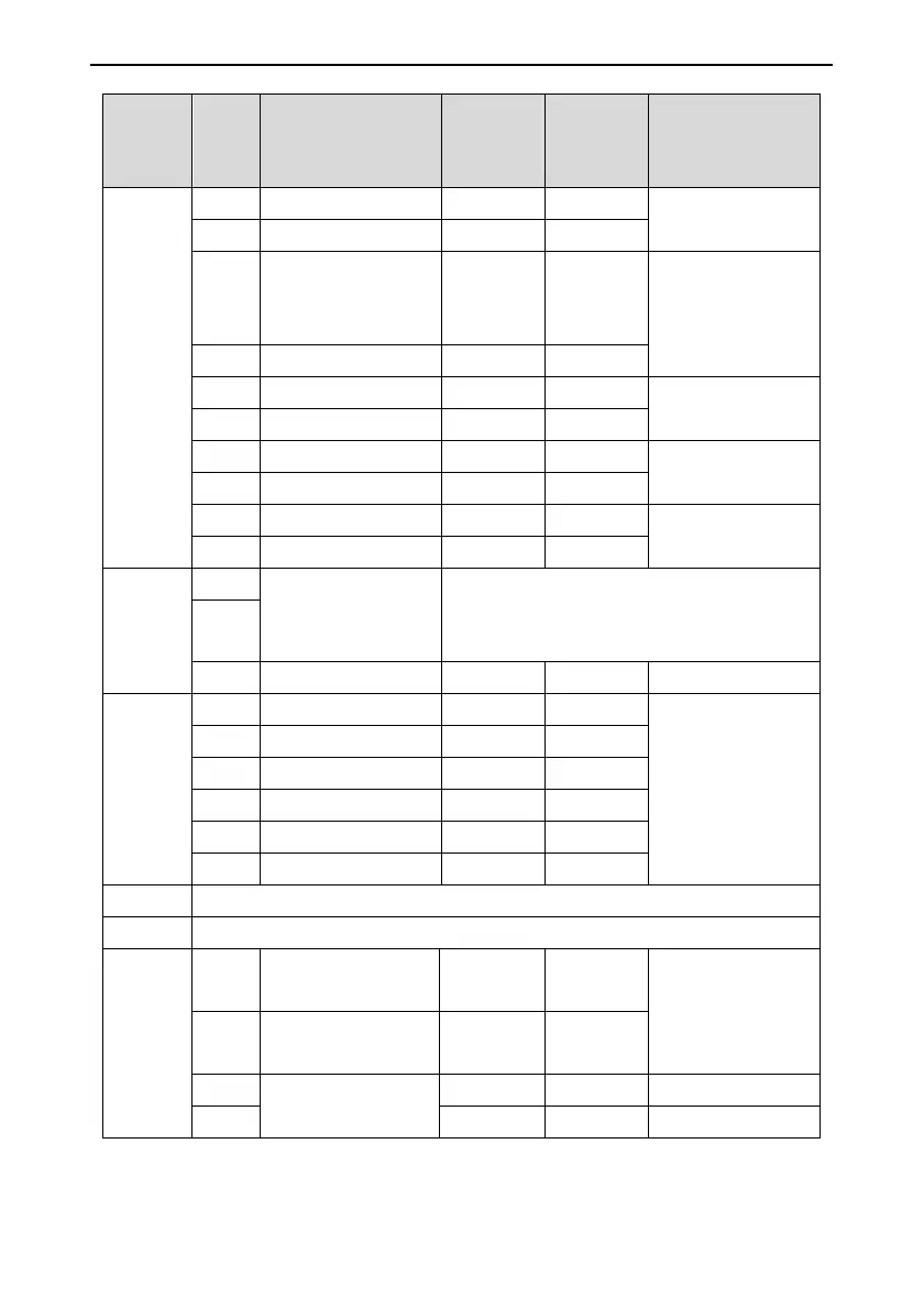
Plug-in
No.
Pin
No.
Terminal definition Code
LED
indicator
code
Remarks
output 250VAC
COM2 Y2 common terminal COM2
Y3
Star-delta contactor
output (synchronous
tractor)
Y3 LED36
Relay NO output 5A,
250VAC
COM3 Y3 common terminal COM3
Y4 FR fire forced output Y4 LED37
Relay NO output 5A,
250VAC
COM4 Y4 common terminal COM4
Y5 MF defined output 1 Y5 LED32
Relay NO output 5A,
250VAC
COM5 Y5 common terminal COM5
Y6 MF defined output 2 Y6 LED33
Relay NO output 5A,
250VAC
COM6 Y6 common terminal COM6
CN8
terminals
1-3
GPRH
CAN2 bus differential
signal
CAN2 communication interface, for parallel
connection and group control: the default terminal
resistance is about 120Ω.
GPRL
COM
CN9
terminals
1-6
12V Encoder power 12V
Encoder terminal of
asynchronous
master, supply
DC12V power
PGM Encoder power 0V
PGA Encoder input A phase
PGB Encoder input B phase
PGM Encoder power 0V
PE Grounding terminal
CN10 Encoder terminal of synchronous master (apply for ECN1387), see wiring diagram.
CN11 Connecting terminal of PG card (apply for ECN1313 encoder or rotary transformer)
CN15
1-4
AI1
Positive analog input
terminal
AI1
Input impedance:
10Ω;
Voltage range: 0~10V
GND
Negative analog input
terminal
GND
485+
RS485 differential
signal
485+ For monitoring
485- 485- For monitoring