123
ADDR 01H
CMD 03H
Byte number 04H
Data high bit of address 0004H 13H
Data low bit of address 0004H 88H
Data high bit of address 0005H 00H
Data low bit of address 0005H 00H
CRC CHK low bit 7EH
CRC CHK high bit 9DH
END T1-T2-T3-T4 (transmission time of 3.5 bytes)
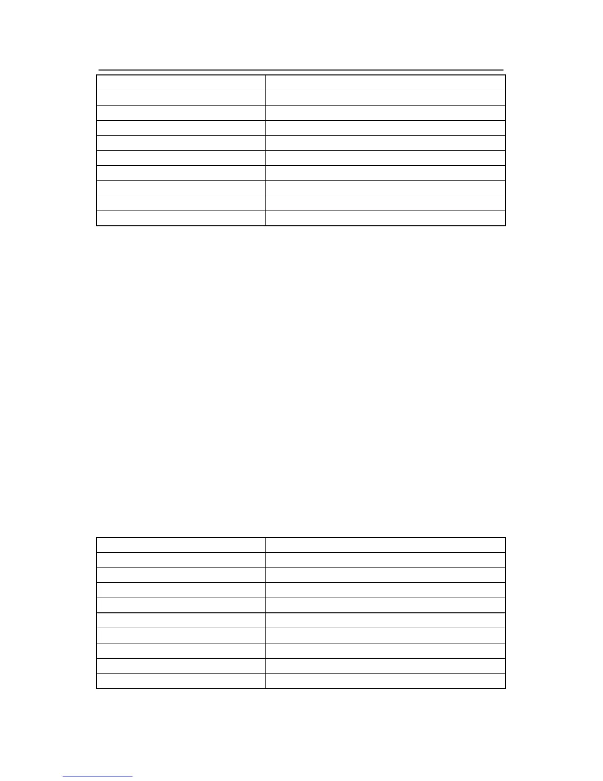
The meaning of the response is that:
ADDR = 01H means the command message is sent to the inverter with the address of 01H
and ADDR occupies one byte
CMD=03H means the message is received from the inverter to the master for the response
of reading command and CMD occupies one byte
“Byte number” means all byte number from the byte(excluding the byte) to CRC
byte(excluding the byte). 04 means there are 4 byte of data from the “byte number” to “CRC
CHK low bit”, which are “digital address 0004H high bit”, “digital address 0004H low bit”,
“digital address 0005H high bit” and “digital address 0005H low bit”.
There are 2 bytes stored in one data with the fact that the high bit is in the front and the low
bit is in the behind of the message, the data of data address 0004H is 1388H, and the data
of data address 0005H is 0000H.
CRC occupies 2 bytes with the fact that the high bit is in the front and the low bit is in the
behind.
9.4.2 Command code: 06H
06H (correspond to binary 0000 0110), write one word(Word)
The command means that the master write data to the inverter and one command can write
one data other than multiple dates. The effect is to change the working mode of the inverter.
For example, write 5000 (1388H) to 0004H from the inverter with the address of 02H, the
frame structure is as below:
RTU master command message (from the master to the inverter)
START T1-T2-T3-T4(transmission time of 3.5 bytes)
ADDR 02H
CMD 06H
High bit of write data address 00H
Low bit of write data address 04H
High bit of data content
13H
Low bit of data content
88H
CRC CHK low bit C5H
CRC CHK high bit 6EH
END T1-T2-T3-T4 (transmission time of 3.5 bytes)
RTU slave response message (from the inverter to the master)