Goodrive200A inverters Installation guidelines
18
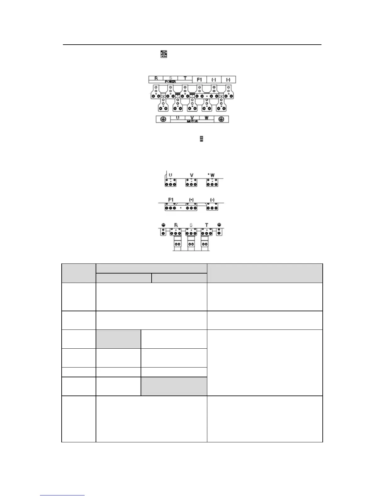
Fig 4-14 220~315kW terminals of main circuit
Fig 4-15 350~500kW terminals of main circuit
Terminal
Terminal name
Function
≤30kW ≥37kW
R, S, T
Power input of the main circuit
3-phase AC input terminals which are
generally connected with the power
supply.
U, V, W
The inverter output
3-phase AC output terminals which are
generally connected with the motor.
P1
This terminal is
inexistent
DC reactor terminal 1
P1 and (+) are connected with the
terminals of DC reactor.
(+) and (-) are connected with the
terminals of braking unit.
PB and (+) are connected with the
terminals of braking resistor.
(+)
Braking
1
DC reactor terminal 2,
braking unit terminal 1
(-) / Braking unit terminal 2
terminal 2
This terminal is
inexistent.
PE
380V:the grounding resistor is less
than 10Ohm
Protective grounding terminals, every
machine is provided 2 PE terminals as
the standard configuration. These
terminals should be grounded with
proper techniques.