Control power supply terminal
Optional parts (external 220V control
power supply)
Note:
Do not use an asymmetrically constructed motor cable. If there is a symmetrically
constructed grounding conductor in the motor cable in addition to the conductive
shield, connect the grounding conductor to the grounding terminal at the inverter
and motor ends.
Braking resistor, braking unit and DC reactor are optional parts.
Route the motor cable, input power cable and control cables separately.
If the terminal is not appeared, the machine does not provide the terminal as the
external terminal.
4.3.3 Wiring of terminals in main circuit
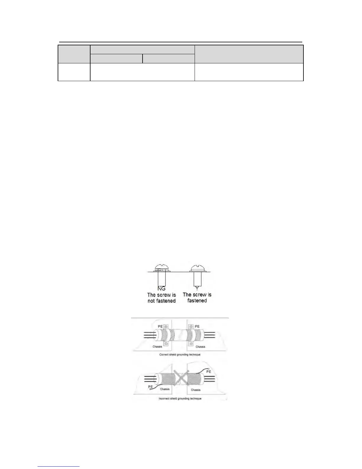
1. Fasten the grounding conductor of the input power cable with the grounding terminal of
the inverter (PE) by 360 degree grounding technique. Connect the phase conductors to R, S
and T terminals and fasten.
2. Strip the motor cable and connect the shield to the grounding terminal of the inverter by
360 degree grounding technique. Connect the phase conductors to U, V and W terminals
and fasten.
3. Connect the optional brake resistor with a shielded cable to the designated position by the
same procedures in the previous step.
4. Secure the cables outside the inverter mechanically.
Fig 4-16 Correct installation of the screw
Fig 4-17 360 degree grounding technique