0: Decelerate to stop: after the stop command
becomes valid, the inverter decelerates to reduce
the output frequency during the set time. When
the frequency decreases to 0Hz, the inverter
stops.
1: Coast to stop: after the stop command
becomes valid, the inverter ceases the output
immediately. And the load coasts to stop at the
mechanical inertia.
0 ○
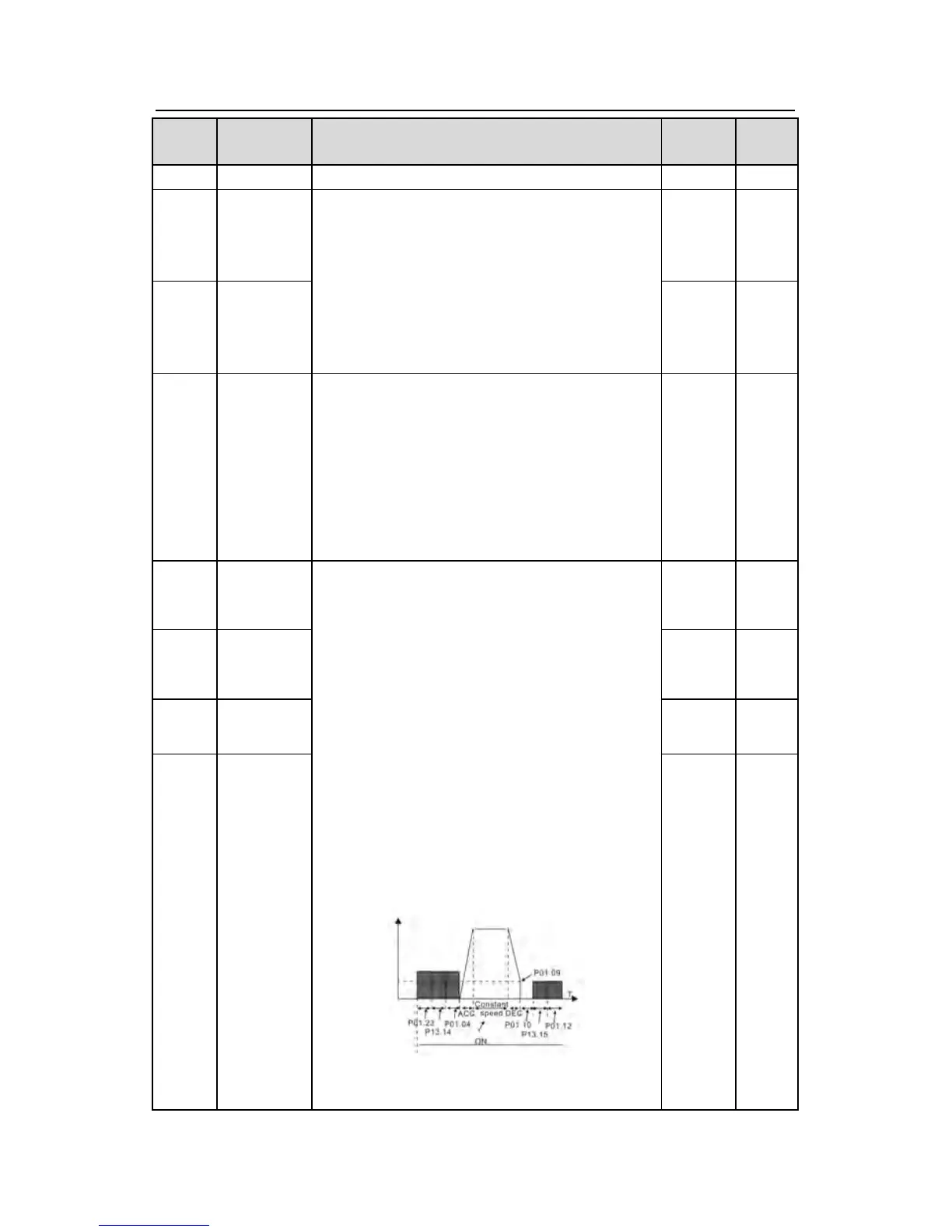
P01.09
Starting frequency of DC braking: start the DC
braking when running frequency reaches starting
frequency determined by P1.09.
Waiting time before DC braking: Inverters block
the output before starting the DC braking. After
this waiting time, the DC braking will be started
so as to prevent over-current fault caused by DC
braking at high speed.
DC braking current:The value of P01.11 is the
percentage of rated current of inverter. The
bigger the DC braking current is, the greater the
braking torque is.
DC braking time: The retention time of DC brake.
If the time is 0, the DC brake is invalid. The
inverter will stop at the set deceleration time.
Setting range of P01.09: 0.00Hz~P00.03
(the Max. frequency)
0.00Hz