Goodrive200A inverters Function parameters
90
Function
code
Name Detailed instruction of parameters
Default
value
voltage Range: 0.0~2000.0V
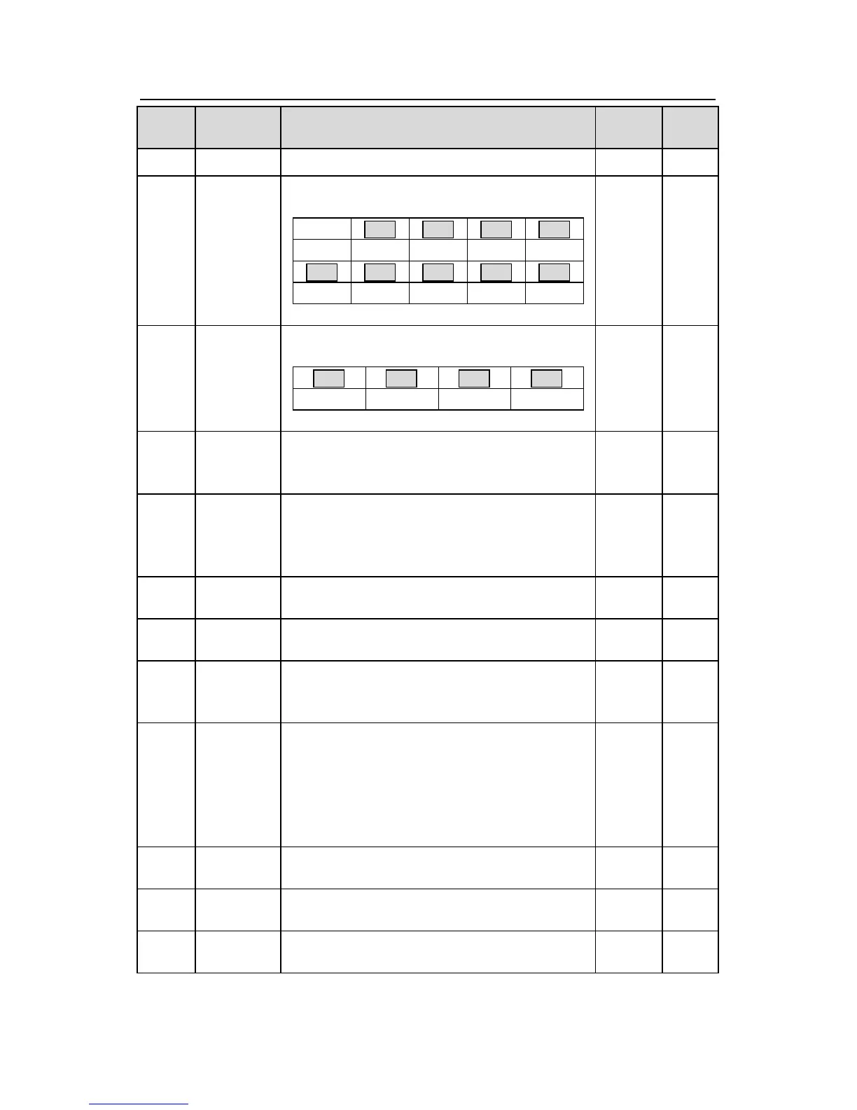
P17.12
ON-OFF
input
terminals
state
Display current Switch input terminals state of the
inverter
BIT8
S5 S4 S3 S2 S1
Range: 0000~00FF
●
P17.13
ON-OFF
output
terminals
state
Display current Switch output terminals state of
the inverter
BIT3 BIT2 BIT1 BIT0
RO2 RO1 HDO Y
Range: 0000~000F
●
P17.14
Display the adjustment through the keypad of the
inverter.
Range : 0.00Hz~P00.03
●
P17.15
Display the torque given, the percentage to the
current rated torque of the motor.
Setting range: -300.0%~300.0%
(the rated current of the motor)
●
P17.16
Display the current linear speed of the inverter.
Display the current length of the inverter.
Range: 0~65535
●
P17.18
Counting
value
Display the current counting number of the
inverter.
Range: 0~65535
●
P17.19
AI1 input
voltage
The inverter(≤15kW) can be set by the analog
potentiometer on the keypad and AI1 setting is
not available for the device which is 18.5kW or
higer than 18.5 kW.
Display analog AI1 input signal
Range: 0.00~10.00V
●
P17.20
AI2 input
voltage
Display analog AI2 input signal
Range: 0.00~10.00V
●
P17.21
AI3 input
voltage
Display analog AI2 input signal
Range: -10.00~10.00V
●
P17.22
Display HDI input frequency
Range: 0.000~50.000kHz
●