EasyManua.ls Logo

INVT Goodrive10 Series User Manual

INVT Goodrive10 Series
125 pages
To Next Page IconTo Next Page
To Previous Page IconTo Previous Page
Page #106 background imageLoading...
Page #106 background image
Goodrive10 Series Mini VFD Communication protocol
-101-
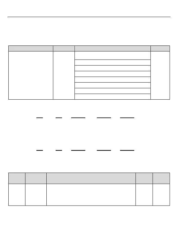
7.3.7.2 Examples of writing command 06H
Make the VFD with the address of 03H to run forward. See section 7.3.4.2 “Description of
other function addresses in Modbus”, the address of “Communication-based control
command” is 2000H and forward running is 0001.
Function
Address
Data description
R/W
Communication-based
control command
2000H
0001H: Forward running
R/W
0002H: Reverse running
0003H: Forward jogging
0004H: Reverse jogging
0005H: Stop
0006H: Coast to stop (emergency stop)
0007H: Fault reset
0008H: Jogging to stop
The command sent by the master:
Parameter
address
CRC
check
VFD
address
Write
command
Forward
running
03 06 20 00 00 01 42 28
If the operation is successful, the response may be as below (the same with the command
sent by the master):
Parameter
address
CRC
check
VFD
address
Write
command
Forward
running
03 06 20 00 00 01 42 28
Set max. output frequency of the VFD with the address of 03H as 100Hz.
Function
code
Name
Description
Default
Modify
P00.03
Max.
output
frequency
Used to set max. output frequency of the VFD. It is
the basis of frequency setup and the
acceleration/deceleration.
Setting range: P00.04400.00Hz
50.00Hz
See the figures behind the radix point, the fieldbus ratio value of max. output frequency
(P00.03) is 100. 100Hz timed by 100 is 10000 and the corresponding hex is 2710H.
The command sent by the master:

Table of Contents

Question and Answer IconNeed help?

Do you have a question about the INVT Goodrive10 Series and is the answer not in the manual?

INVT Goodrive10 Series Specifications

General IconGeneral
BrandINVT
ModelGoodrive10 Series
CategoryInverter
LanguageEnglish

Summary

1 Safety Precautions

1.1 Safety Definitions and Warning Symbols

Defines safety terms like Danger, Warning, Note, and explains warning symbols used in the manual.

1.3 Safety Guidelines

Outlines general safety rules for VFD operation, installation, commissioning, and maintenance.

2 Product Overview

2.1 Quick Start and Initial Setup

Guides through initial VFD setup: unpacking, application confirmation, environment, and basic commissioning.

2.2 Product Specifications

Detailed technical specifications including input/output, control, and peripheral performance.

2.4 Model Code and Rated Specifications

Explanation of the VFD model code structure and a table of rated electrical specifications.

2.6 VFD Structure Diagram

Diagram and description of the VFD's physical components and their functions.

3 Installation Guidelines

3.1 Mechanical Installation

Guidelines for physically mounting the VFD, including environment and direction.

3.2 Electrical Installation

Instructions for wiring main and control circuits, including terminal identification.

3.3 Wiring Protection

Methods for protecting the VFD, input power cable, and motor cables from electrical issues.

4 Keypad Operation

4.1 Keypad Overview

Introduction to the VFD keypad, its connection, and basic functions.

4.2 Keypad Display Elements

Explanation of the keypad's display, LEDs, and code display zone.

4.3 Keypad Operations

Detailed procedures for operating the VFD using the keypad, including parameter modification.

5 Function Parameters

P00 Group: Basic Functions

Parameters for fundamental VFD operations like speed control, command sources, and frequency limits.

P01 Group: Start and Stop Control

Parameters controlling VFD startup modes, braking, and stopping behavior.

P02 Group: Motor Parameters

Parameters for configuring motor characteristics to optimize VFD control performance.

P04 Group: SVPWM Control

Parameters related to SVPWM control, including V/F curves and torque boost settings.

P05 Group: Input Terminals Configuration

Configuration of digital and analog input terminals for control and frequency setting.

P07 Group: HMI Parameters

Parameters related to the Human-Machine Interface, including keypad settings and fault display.

P09 Group: PID Control Parameters

Parameters for setting up and tuning the Proportional-Integral-Derivative (PID) control loop.

P10 Group: Multi-Step Speed Control

Parameters for configuring multiple speed steps and their selection logic.

P11 Group: Protection Parameters

Parameters for VFD protection functions like overvoltage, overcurrent, and overload protection.

P14 Group: Serial Communication Settings

Parameters for configuring serial communication using protocols like Modbus RTU.

P17 Group: Status Viewing Parameters

Parameters used to display the VFD's real-time operational status and values.

6 Fault Tracking

6.1 Fault Prevention and Maintenance

Methods for preventing VFD faults through regular maintenance and component checks.

6.2 Fault Handling Procedures

Steps and information for identifying, resetting, and resolving VFD fault conditions.

7 Communication Protocol

7.1 Modbus Protocol Overview

Introduction to the Modbus protocol and its application in VFD communication.

7.2 VFD Application Modes

Details on Modbus RTU mode and 2-wire RS485 communication interface.

7.3 RTU Command Codes & Data Description

Description of Modbus RTU command codes, data formats, and error checks.

Appendix A Technical Data

A.1 Derating in Application

Information on VFD derating due to temperature, altitude, and carrier frequency.

A.2 CE Compliance Information

Details on CE marking, EMC compliance, and EMC regulations for VFDs.

Appendix B Dimension Drawings

B.1 Keypad Structure Diagram

Diagram showing the physical structure and dimensions of the VFD keypad.

B.2 VFD Dimensions Chart

Table detailing wall-mounting dimensions for various VFD models.

Appendix C Optional Peripheral Accessories

C.1 Peripheral Wiring Diagram

Diagram illustrating typical peripheral wiring connections for the VFD.

C.3 Cable Selection Guidelines

Recommendations for selecting power and control cables, including size and shielding.

C.4 Breaker and Contactor Selection

Guidance on selecting circuit breakers and contactors for VFD protection.

C.5 Reactor Selection

Selection criteria for input and output reactors to enhance VFD performance.

C.6 Filter Selection

Information on selecting input and output filters for VFD interference reduction.

C.7 Braking System

Information on braking units and resistor selection for VFD applications.

Appendix D Further Information

D.1 Product & Service Inquiries

Contact information for product and service support from INVT.

D.3 Online Documents

Guidance on finding VFD manuals and product documents on the internet.

Related product manuals