Goodrive10 Series Mini VFD Installation guidelines
-17-
1. Output range:0–10V or 0–20mA
2. The voltage or the current output is depended on J2
3. Deviation±1%, 25°C
1. Internal impedance:3.3kΩ
2. 0–4V corresponds to low electric level input and
7–30V corresponds to high electric level input
3. Max input frequency:1kHz
4. All terminals are programmable digital input
terminals. User can set the terminal function through
function codes.
Common terminal for S5/Y and switch by J1
Note: S5 and Y can not be used at the same time
RS485 communication/differential signal port. The standard RS485
communication interface should use twisted shielded pair
3.3 Wiring protection
3.3.1 Protect the VFD and input power cable in short-circuit situations
Protect the VFD and input power cable during short-circuit to aviod thermal overload.
Carry out protective measures according to the following requirements.
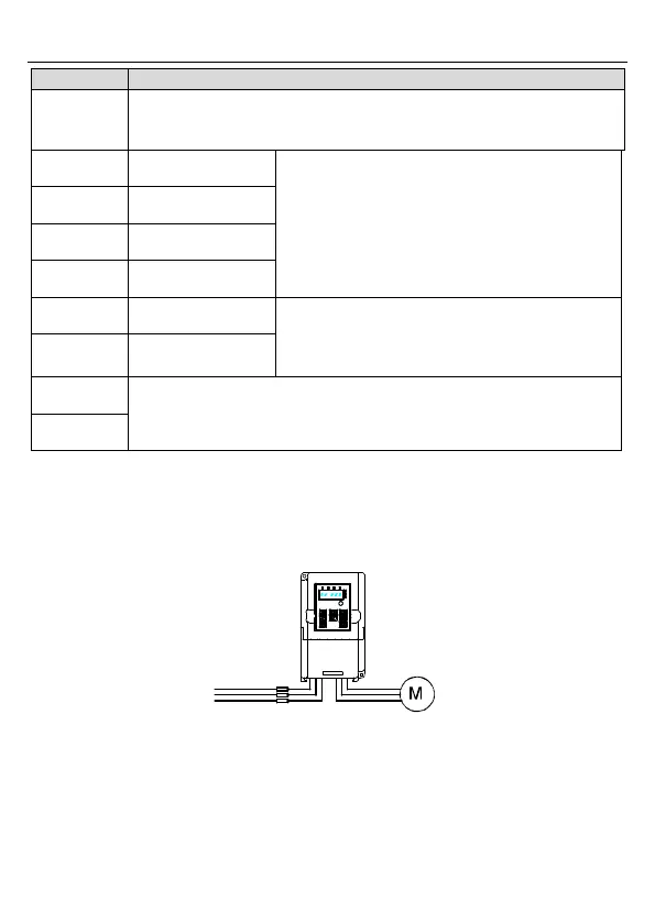
Figure 3-7 Fuse configuration
Note: Select the fuse according to operation manual. During short-circuit, the fuse will
protect input power cables to avoid damage to the VFD; when internal short-circuit occurred
to the VFD, it can protect neighboring equipment from being damaged.

 Loading...


