Goodrive10 Series Mini VFD Keypad operation
-19-
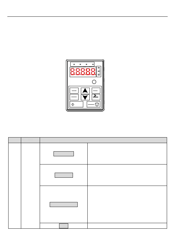
4 Keypad operation
4.1 Keypad introduction
You can use the keypad to control the start and stop, read status data, and set parameters
of the VFD. The keypad can be externally connected to the VFD, which requires a network
cable with a standard RJ45 crystal head as the connection cable.
1
2
4
3
5
RUN/TUNE
FWD/REV
LOCAL/REMOT
TRIP
Hz
A
V
RPM
%
PRG
ESC
QUICK
JOG
DATA
ENT
SHIFT
STOP
RST
RUN
Figure 4-1 Keypad diagram
Note: Fix the external keypad with M3 screws or keypad installation bracket. The installation
bracket is optional.
LED off means that the VFD is in the
stopping state; LED blinking means the VFD
is in the parameter autotune state; LED on
means the VFD is in the running state.
FED/REV LED
LED off means the VFD is in the forward
rotation state; LED on means the VFD is in
the reverse rotation state
LED for keypad operation, terminals
operation and remote communication control
LED off means that the VFD is in the keypad
operation state; LED blinking means the
VFD is in the terminals operation state; LED
on means the VFD is in the remote
communication control state.

 Loading...


