EasyManuals Logo
Home>INVT>Inverter>Goodrive10 Series

INVT Goodrive10 Series User Manual

INVT Goodrive10 Series
125 pages
To Next Page IconTo Next Page
To Previous Page IconTo Previous Page
Page #15 background imageLoading...
Page #15 background image
Goodrive10 Series Mini VFD Product overview
-10-
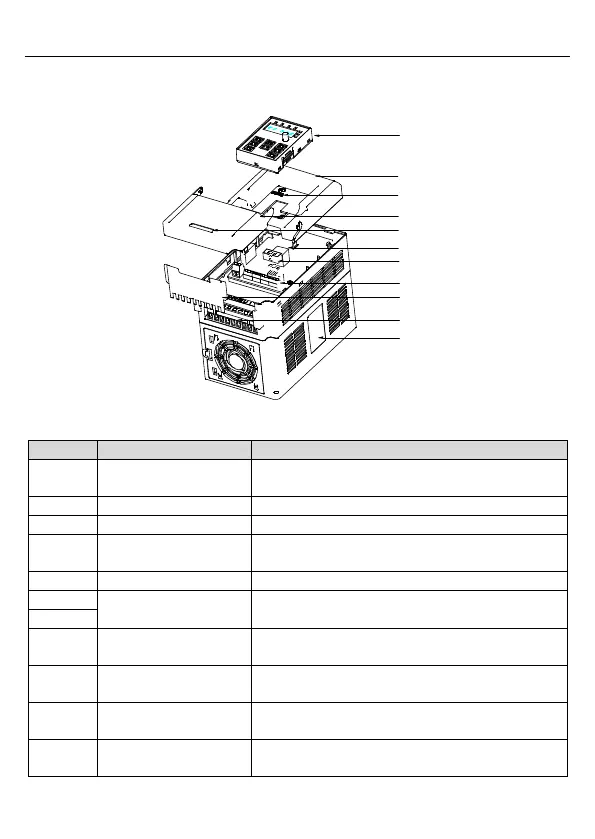
2.6 Structure diagram
Figure 2-3 shows the structure of the VFD (taking the VFD of 2.2kW as an example).
1
2
3
4
5
6
7
8
9
10
11
Figure 2-3 Product structure diagram
No.
Name
Description
1
Keypad
See Chapter 4 "Keypad operation" for detailed
information.
2
Cover
To protect the internal parts and components.
3
POWER indicator
POWER indicator
4
Flip-open cover
To protect the internal components, turnover for
wiring.
5
Simple nameplate
See section 2.4 "Mode code" for detailed information.
6
Keypad port
To connect the keypad.
6 is used for external installation.
7
8
Control circuit terminals
See section 3.2 "Electrical installation" for detailed
information.
9
Bobbin winder
To protect the internal parts and components,
detachable for wiring.
10
Main circuit terminals
See section 3.2 "Electrical installation" for detailed
information.
11
Nameplate
See section 2.3 "Product nameplate" for detailed
information.

Table of Contents

Questions and Answers:

Question and Answer IconNeed help?

Do you have a question about the INVT Goodrive10 Series and is the answer not in the manual?

INVT Goodrive10 Series Specifications

General IconGeneral
BrandINVT
ModelGoodrive10 Series
CategoryInverter
LanguageEnglish

Related product manuals