Goodrive10 Series Mini VFD Optional peripheral accessories
-108-
Appendix C Optional peripheral accessories
This chapter describes how to select the options and parts of Goodrive10 series VFDs.
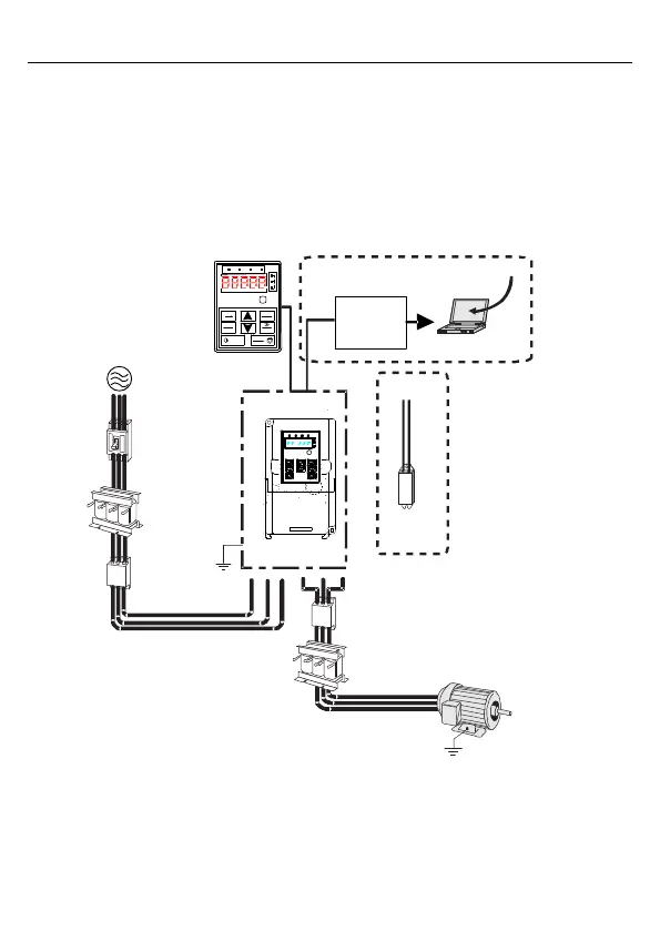
C.1 Peripheral wiring
Figure C-1 shows the peripheral wiring of Goodrive10 series VFDs.
+
PB
RS485–
RS232
converter
485+
485-
Keypad
Power
supply
Breaker
Input reactor
Input filter
Grounding
PC
Upper computer
software
Brake resistor
Output filter
Output reactor
Motor
Grounding
1
2
4
3
5
PRG
ESC
DATA
ENT
QUICK
JOG
SHIFT
RUN
STOP
RST
RUN/TUNE FWD/REV LOCAL/REMOT TRIP
Hz
A
V
RPM
%
Note: If C3 input filter is selected, C3 input filter is connected in parallel to input end of the
VFD.

 Loading...


