Goodrive10 Series Mini VFD Optional peripheral accessories
-118-
Do not use braking resistors whose resistance is lower than the
specified minimum resistance. VFDs do not provide protection against
overcurrent caused by resistors with low resistance.
In scenarios where braking is frequently implemented, that is, the
braking usage is greater than 10%, you need to select a braking resistor
with higher power as required by the operation conditions according to
the preceding table.
C.7.3 Braking resistor installation
Braking resistor cables shall be shielded cables.
All resistors must be installed in places with good cooling conditions. Braking resistors are
connected externally.
The materials near the braking resistor must be non-flammable. The
surface temperature of the resistor is high. Air flowing from the resistor is
of hundreds of degrees Celsius. Prevent any materials from coming into
contact with the resistor.
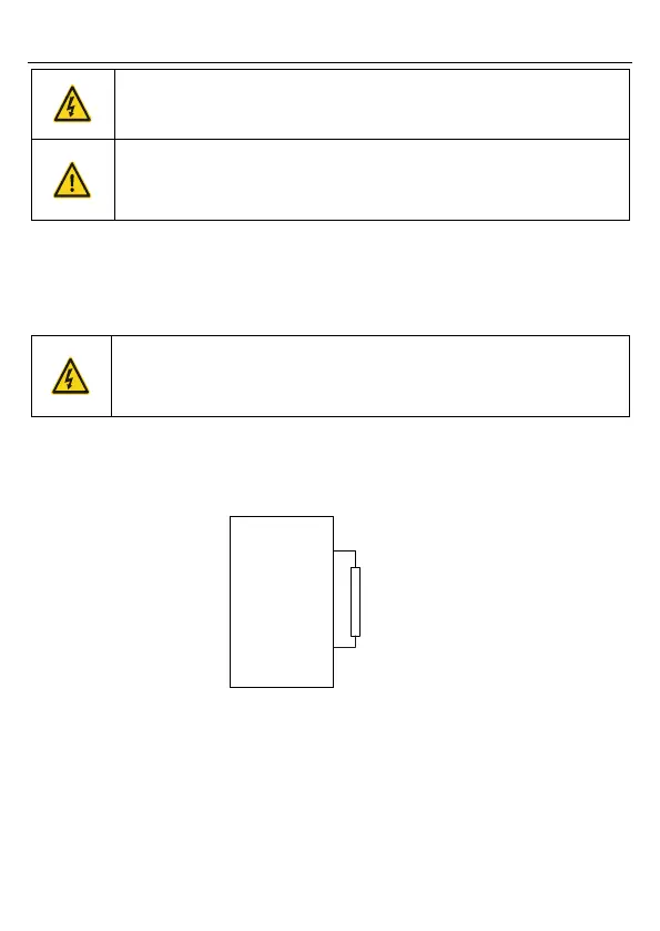
Goodrive10 series VFD need only external braking resistors. PB and (+) are the terminals
for connecting braking resistors. Installation of braking resistors is shown in the following
figure.
PB
External
braking
resistor
Goodrive10
(+)

 Loading...


