Goodrive10 Series Mini VFD Keypad operation
-21-
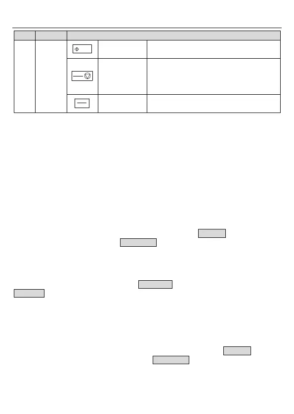
This key is used to operate on the VFD in
key operation mode
This key is used to stop in running state and
it is limited by function code P07.04
This key is used to reset all control modes in
the fault alarm state
The function of this key is confirmed by
function code P07.02.
4.2 Keypad display
The keypad of Goodrive10 series VFD displays the stopped-state parameters, running-state
parameters, function parameter editing status, and fault alarm status.
4.2.1 Displaying stopped-state parameters
When the VFD is in stopped state, the keypad displays stopped-state parameters.
In the stopped state, parameters in various states can be displayed. You can determine
which parameters are displayed by setting the binary bits of P07.07. For definitions of the
bits, see the description of P07.07.
In stopping state, there are 10 parameters that can be selected for display, including set
frequency, bus voltage, input terminal state, output terminal state, PID reference, PID
feedback, AI1, AI2, current step of multi-step speed, and pulse counting. P07.07 can select
the parameter to be displayed or not by bit, and you can press 》/SHIFT to shift selected
parameters from left to right or press QUICK/JOG to shift selected parameters from right to
left.
4.2.2 Displaying running-state parameters
After receiving a valid running command, the VFD enters the running state, and the keypad
displays running-state parameters, with the RUN/TUNE indicator on. The on/off state of the
FWD/REV indicator is determined by the current running direction.
In running state, there are 20 parameters that can be selected for display, including running
frequency, set frequency, bus voltage, output voltage, output current, running speed, output
power, output torque, PID reference PID feedback, input terminal state, output terminal state,
pulse counting, current step of multi-step speed, AI1, AI2, motor overload percentage, VFD
overload percentage, ramp frequency reference, and linear speed. P07.05 and P07.06 can
select the parameter to be displayed or not by bit, and you can press 》/SHIFT to shift
selected parameters from left to right or press QUICK/JOG to shift selected parameters
from right to left.

 Loading...


