EasyManuals Logo
Home>INVT>Inverter>Goodrive10 Series

INVT Goodrive10 Series User Manual

INVT Goodrive10 Series
125 pages
To Next Page IconTo Next Page
To Previous Page IconTo Previous Page
Page #25 background imageLoading...
Page #25 background image
Goodrive10 Series Mini VFD Keypad operation
-20-
No.
Name
Description
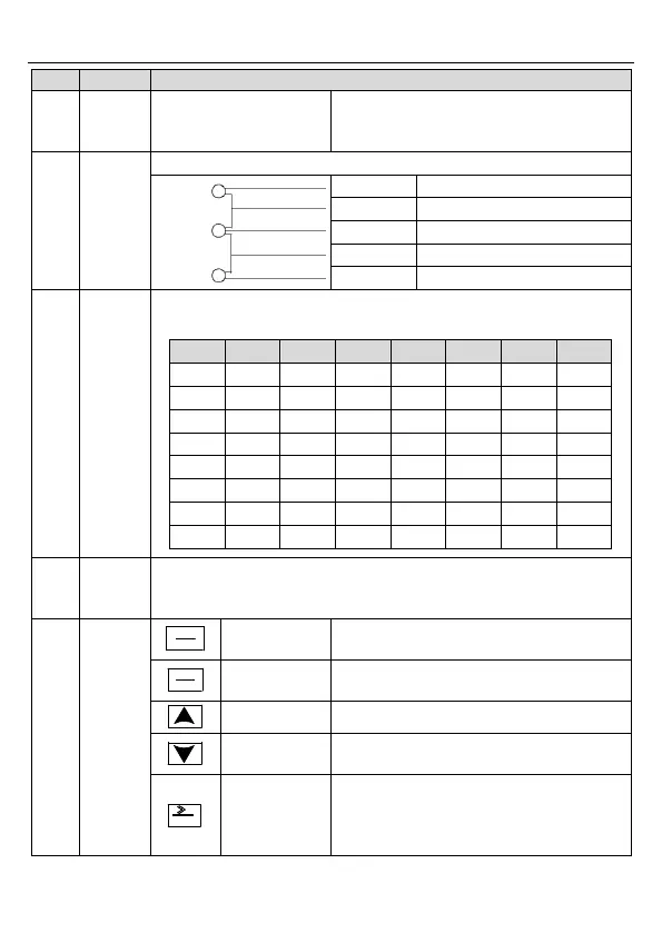
LED on when the VFD is in the fault state;
LED off in normal state; LED blinking means
the VFD is in the overload pre-alarm state.
2
Unit LED
Mean the unit displayed currently
Hz
Frequency unit
A
Current unit
V
Voltage unit
RPM
Rotating speed unit
%
Percentage
3
Code
displayin
g zone
5-figure LED display displays various monitoring data and alarm code
such as set frequency and output frequency.
Display
Means
Display
Means
Display
Means
Display
Means
0
0
1
1
2
2
3
3
4
4
5
5
6
6
7
7
8
8
9
9
A
A
B
B
C
C
D
D
E
E
F
F
H
H
I
I
L
L
N
N
n
n
o
o
P
P
r
r
S
S
t
t
U
U
v
v
.
.
-
-
4
Digital
potentio
meter
Corresponds to AI1.
5
Buttons
PRG
ESC
Programming
key
Enter or escape from the first level menu and
remove the parameter quickly
DATA
ENT
Entry key
Enter the menu step-by-step
Confirm parameters
UP key
Increase data or function code progressively
DOWN key
Decrease data or function code
progressively
SHIFT
Right-shift key
Move right to select the displaying parameter
circularly in stopping and running mode.
Select the parameter modifying digit during
the parameter modification

Table of Contents

Questions and Answers:

Question and Answer IconNeed help?

Do you have a question about the INVT Goodrive10 Series and is the answer not in the manual?

INVT Goodrive10 Series Specifications

General IconGeneral
BrandINVT
ModelGoodrive10 Series
CategoryInverter
LanguageEnglish

Related product manuals