Goodrive10 Series Mini VFD Installation guidelines
-14-
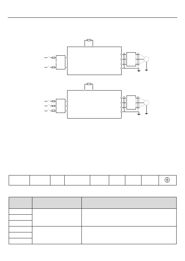
3.2 Electrical installation
3.2.1 Wiringof main circuit
R
S
T
W
V
U
PE
M
(+)
PB
3PH
380V/220V
50/60Hz
Brake resistor
Fuse
L
N
W
V
U
PE
M
(+)
PB
1PH 220V
50/60Hz
Input
reactor
Input
filter
Fuse
Output
reactor
Output
filter
Brake resistor
Input
filter
Input
reactor
Output
filter
Output
reactor
Figure 3-3 Wiring of main circuit
Note:
The fuse, DC reactor, braking resistor, input reactor, input filter, output reactor, output
filter are optional parts. Refer to Appendix C "Optional peripheral accessories" for
detailed information.
Before connecting the braking resistor cable, remove the yellow labels of PB, (+), and (-)
from the terminal blocks. Otherwise, poor connection may occur.
3.2.2 Main circuit terminals
Figure 3-4 Main circuit terminal diagram
3PH/1PH AC input terminals, connected to the grid.
3PH AC output terminals, connected to the motor.

 Loading...


