Goodrive10 Series Mini VFD Installation guidelines
-16-
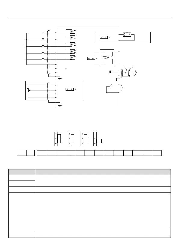
3.2.4 Wiring of control circuit
GND
GND
Multi-function input terminal 1
Multi-function input terminal 2
Multi-function input terminal 4
Multi-function input terminal 5
Multi-function input terminal 3
Analog output
RO1
Shielding wire
Twisted pairs
RS485
communication
0-10V/0-20mA
+10V
AI1
S1
S2
S3
S4
S5/Y
24V
PE
AO1
GND
J2
485+
485-
GND
PE
ROA
ROC
V I
PE
Power supply for
frequency setting
J1
S5 Y
J4
V I
J3
GND
Y
Open collector
output
Figure 3-5 Wiring of control circuit
3.2.5 Control circuit terminals
S5/Y AO AI 485
ROA
ROC
24V
S1 S2 S3 S4 S5/Y GND
I
V
O
I
I
V
ON
J1 J2 J3 J4
GND AI AO 10V 485+ 485-
Figure 3-6 Control circuit terminal diagram
RO relay output
Contactor capability: 3A/AC250V,1A/DC30V
1. Input range: AI voltage and curren: 0–10V/0–20mA and switch by J3
2. Input impedance:voltage input: 20kΩ; current input: 500Ω
3. Resolution: the minimum one is 5mV when 10V corresponds to 50Hz
4. Deviation ±1%, 25°C
Note: Keypad potentiometer set AI1parameters of and AI terminal set AI2
parameters.
Local +24V power supply, 100mA
+10V reference zero potential

 Loading...


