Goodrive10 Series Mini VFD Function parameters
-48-
Output
terminal
polarity
selection
The function code is used to set the polarity of
output terminals.
When the bit is set to 0, the input terminal is
positive.
When the bit is set to 1, the input terminal is
negative.
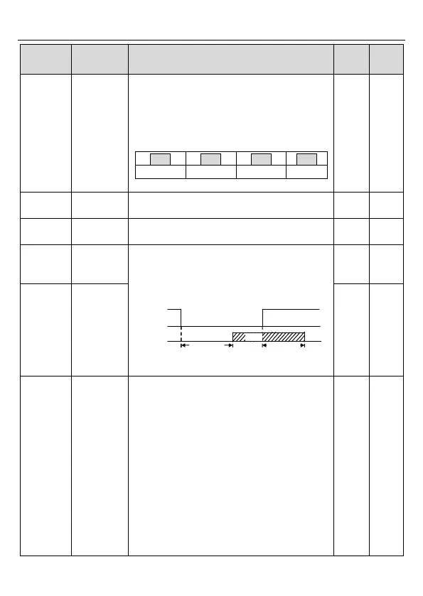
The function code defines the delay time
corresponding to the electrical level changes
when the programmable output terminals switch
on or switch off.
RO electric level
RO valid Invalid
Switch on
delay
invalid
Valid
Switch off
delay
Setting range :0.000–50.000s
0: Running frequency
1: Set frequency
2: Ramp reference frequency
3: Running rotation speed (relative to twice the
rotating speed of the motor)
4: Output current (relative to twice the rated
current of the VFD)
5: Output current (relative to twice the rated
current of the motor)
6: Output voltage (relative to 1.5 times the rated
voltage of the VFD)
7: Output power (relative to twice the rated power
of the motor)
8: Set torque (relative to twice the rated torque of

 Loading...


