Goodrive10 Series Mini VFD Communication protocol
-86-
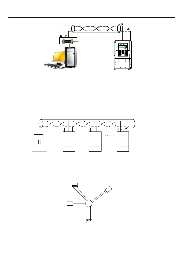
Shielded twisted pair
Ground
Ground
Computer
RS485 line
RS232– RS485
converter
485- 485+
VFD
Figure 7-1 RS485 wiring diagram for the network with one VFD
7.2.1.2 When multiple VFDs are used
In the network with multiple VFDs, chrysanthemum connection and star connection are
commonly used. According to the requirements of the RS485 industrial bus standards, all
the devices need to be connected in chrysanthemum mode with one 120 Ω terminal resistor
on each end, as shown in Figure 7-2.
VFD VFD VFD
Address 1
Address n
Earth
485 +
485 -
Earth
485 +
485 -
Earth
485 +
485 -
120 Ohm
Terminal resistor
Computer
Conv
erter
GND
RS232-485
Max length of
RS: 15m
.
Twisted pair cables with shield screen
Address 2
Figure 7-2 Practical application diagram of chrysanthemum connection
Figure 7-3 shows the start connection diagram. When this connection mode is adopted, the
two devices that are farthest away from each other on the line must be connected with a
terminal resistor (in this figure, the two devices are devices 1# and 15#).
1#
15#
32#
6
#
Main
control
devices
Figure 7-3 Star connection

 Loading...


