EasyManuals Logo

INVT Goodrive18 Series User Manual

INVT Goodrive18 Series
157 pages
To Next Page IconTo Next Page
To Previous Page IconTo Previous Page
Page #152 background imageLoading...
Page #152 background image
Goodrive18 series two-in-one VFD Optional peripheral accessories
-147-
VFD model
Screw specifications
Tightening torque (Nm)
RST
U1V1W1/
U2V2W2
PE
RST
U1V1W1/
U2V2W2
PE
GD18-5R5-4-2
M5
M4
M5
2.26
1.5
2.5
GD18-7R5-4-2
M5
M4
M5
2.26
1.5
2.5
L
Dd
D2B
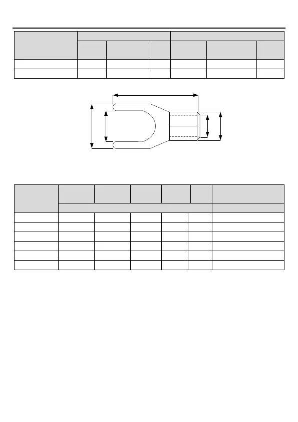
Figure C.1 Y-type terminal diagram
Table C.3 Y-type terminal dimensions
Terminal
model
D2
B
L
Applicable conductor
cross section
Unit: mm
Unit: mm²
Y 1.253
3.2
5.7
16.0
3.4
1.7
0.51.5
YL 1.25-4
4.3
8.1
16.0
3.4
1.7
0.51.5
YL 2-4
4.3
8.1
16.0
4.1
2.3
1.52.5
Y3.5-4
4.3
8.0
18.3
5.0
3.0
2.54
YL5.5-5
5.3
9.0
18.2
5.6
3.4
46
YL 8-5
5.3
9.0
20.8
7.2
4.5
610
Note:
Cables of the sizes recommended for the main circuit can be used in scenarios where the
ambient temperature is lower than 40°C, the wiring distance is shorter than 100 m, and the
current is the rated current.
You are recommended to use the Y-type terminal, of which the "B" size must be shorter
than the main circuit terminal width of the VFD.
If the control cable and power cable must cross each other, ensure that the angle between
them is 90 degrees.
The insulation resistance is reduced if it is damp inside the motor. If it may be damp, you
need to dry the motor and then measure the insulation resistance again.

Table of Contents

Questions and Answers:

Question and Answer IconNeed help?

Do you have a question about the INVT Goodrive18 Series and is the answer not in the manual?

INVT Goodrive18 Series Specifications

General IconGeneral
BrandINVT
ModelGoodrive18 Series
CategoryIndustrial Electrical
LanguageEnglish

Related product manuals