Goodrive18 series two-in-one VFD Optional peripheral accessories
-148-
C.4 Breaker and electromagnetic contactor
You need to add a fuse to prevent overload.
You need to configure a manually manipulated molded case circuit breaker (MCCB) between
the AC power supply and VFD. The breaker must be locked in the open state to facilitate
installation and inspection. The capacity of the breaker needs to be 1.5 to 2 times the rated
current of the VFD.
According to the working principle and structure of breakers, if the
manufaturer's regulation is not followed, hot ionized gases may escape
from the breaker enclosure when a short-circuit occurs. To ensure safe
use, exercise extra caution when installing and placing the breaker.
Follow the manufacturer’s instructions.
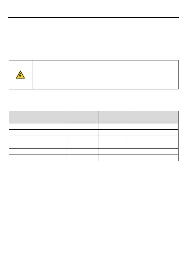
To ensure safty, you can configure an electromeganetic contactor on the input side to control
the switch-on and switch-off of the main circuit power, so that the input power supply of the
VFD can be effectively cut off when a system fault occurs.
Contactor rated
current (A)
C.5 Reactors
When the voltage of the grid is high, the transient large current that flows into the input power
circuit may damage rectifier components. You need to configure an AC reactor on the input
side, which can also improve the current adjustment coefficient on the input side.
When the distance between the VFD and motor is longer than 50 m, the parasitic capacitance
between the long cable and ground may cause large leakage current, and overcurrent
protection of the VFD may be frequently triggered. To prevent this from happening and avoid
damage to the motor insulator, compensation must be made by adding an output reactor.
When the VFD is used to drive multiple motors, take the total length of the motor cables (that
is, sum of the lengths of the motor cables) into account. When the total length is longer than 50
m, an output reactor must be added on the output side of the VFD. If the distance between the
VFD and motor is 50 m to 100 m, select the reactor according to the following table. If the
distance is longer than 100 m, contact INVT technical support.

 Loading...