Goodrive18 series two-in-one VFD Function parameters and function terminal reuse
-79-
proportional effect and differential effect) to
achieve the max. frequency (P00.03) or the max.
voltage (P04.31). Shorter the integral time,
stronger is the adjustment.
Setting range: 0.00–10.00s
High frequency
differential time
(Td)
This function code determines the strength of the
change ratio when PID adjustor carries out
integral adjustment on the deviation of PID
feedback and reference.
If the PID feedback changes 100% during the
time, the adjustment of integral adjustor (ignoring
the proportional effect and differential effect) is
the max. frequency (P00.03) or the max. voltage
(P04.31). Longer integral time indicates stronger
adjusting.
Setting range: 0.00–10.00s
This function code means the sampling cycle of
the feedback. The modulator calculates in each
sampling cycle. A longer sampling cycle
indicates slower response.
Setting range: 0.001–10.000s
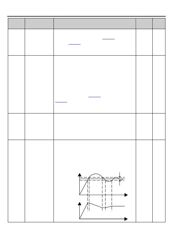
PID control
deviation limit
The output of the PID system is relative to the
maximum deviation of the closed loop reference.
As shown in the following diagram, PID adjustor
stops during the deviation limit. Set this function
code properly to adjust the accuracy and stability
of the PID system.
Output frequency
T
T
Feedback value
Deviation
limit
Reference value

 Loading...