30
Ioline FlexJet User Guide
5. Use the supplied hex wrench to tighten both screws on each
paper hub.
6. Check that the right support block is clear of debris and apply a
light coating of white lithium grease (supplied in the Accessory
Kit.)
7. Lift the feed shaft ends, one at a time, into the support blocks.
Installing the Take-up Shaft
1. If the take-up shaft has plotted markers on it, remove them. See
Removing Markers from the Take-up Shaft later in this chapter.
2. Turn the FlexJet on (the switch is on the back of the left cover.)
3. Use the keypad Unroll key to rotate the take-up key until it is
oriented perpendicular to the support block opening as shown
in Figure 17.
4. Put the take-up shaft into the front support blocks with the
anged coupling at the right (keypad) end. Rotate the shaft
until the slot in the anged coupling is aligned with the take-
up key. When the shaft slot and the key are aligned, push the
take-up shaft into place until it is seated in the support block.
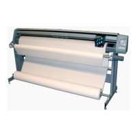
Figure 17. Installing the take-up shaft in the support blocks.
Take-Up Shaft
Use the keypad
to position Take-
Up Key as Shown
Support Block
Rectangular
Slot
Flanged
Coupling
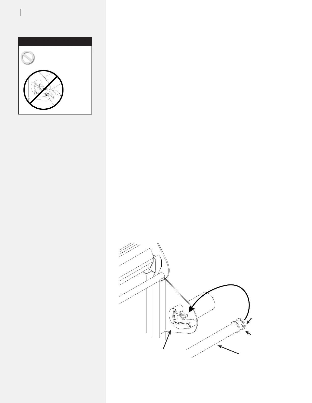
Never touch the take-up
key or anged coupling
while they are rotating.
Serious
personal
injury
could re-
sult. Turn
power off
rst.
Caution