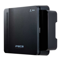
iPECS eMG80
Hardware Description and Installation Manual Issue 1.3
28
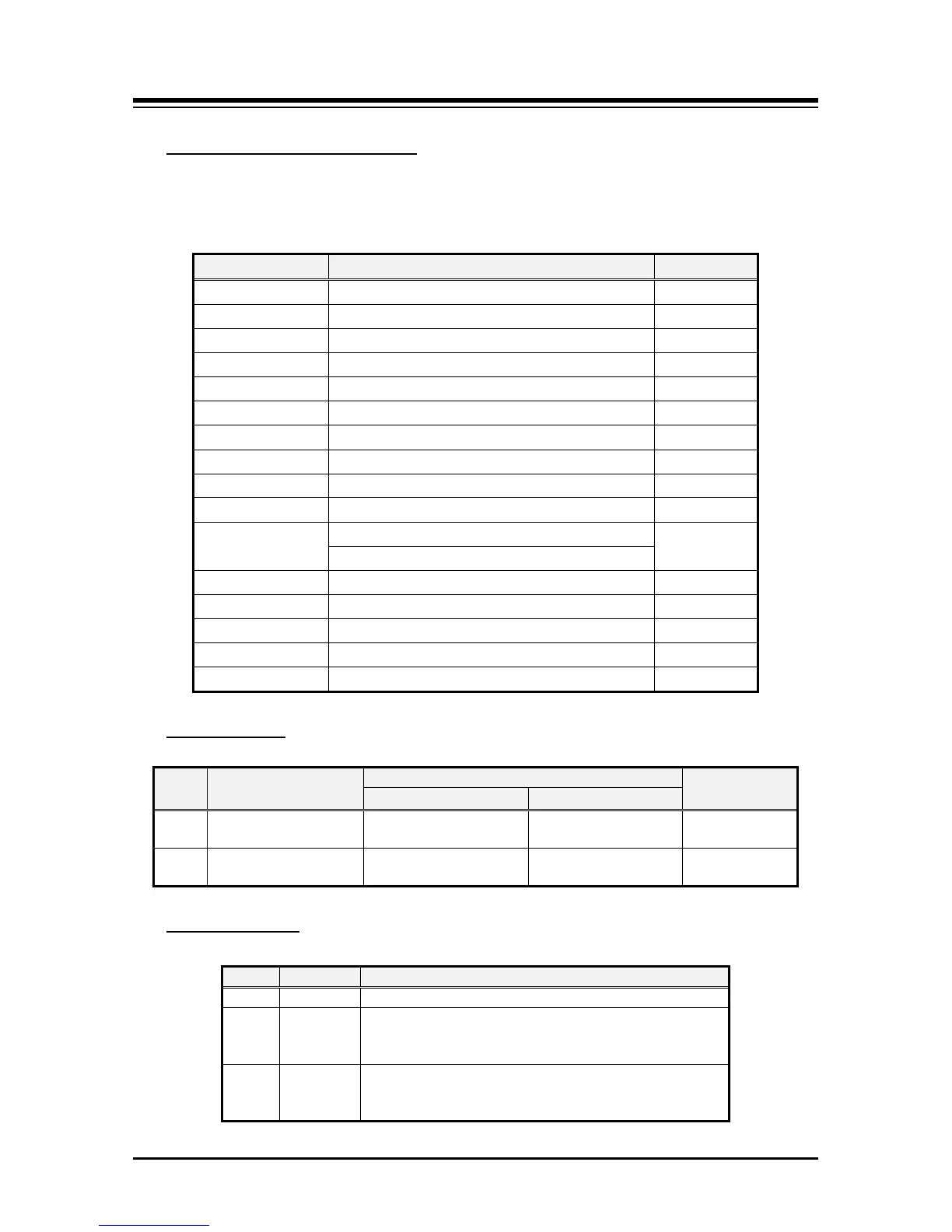
The following chart lists the various connectors for option boards, RJ modular jacks for
connecting CO Lines, Stations and miscellaneous functions, and switches on the Main
Board.
Connectors, Jacks and Switches
Table 4.5.1-1 KSU with MBUA Connector, Modular Jack and Switch Function
Connector Function Remark
CO and Station Interface board installation
CN3 VVMU Installation 32 pins
CN4 MODU Installation 20 pins
CN5 & CN6 Connection KSU to EKSU with Expansion cable 19 pins x 2
CN8 & CN9 MG-CMU4 Installation 8 & 10 pins
CN10 FPGA JTAG for development 10 pins
CN11 RS-232C Port Connection 9 Pins
CN15 MEMU/MEMU2 Installation 20 Pins
MJ1-1 & MJ1-2
CO lines 1 & 2
2 Ports each
CO lines 3 & 4
1 DKT and 7 Hybrid DKT or SLT ports
MJ3 LAN & USB Port 1 LAN/1 USB
MJ4 Relay/Alarm/Page/External MOH Connection 1 port
SW1 2 pole Database protect switch
Push-button System reset switch
Table 4.5.1-2 MBUA SW1 – 2-pole Dip switch
Switch setting
Pole Function
1 Database protection
Protect database, no
admin allowed
Unprotect Default = OFF
2
Initialization for
Use stored Database Default = ON
Table 4.5.1-3 MUBA LED Indication
LED Indications
Flash 300ms ON and OFF, normal operation
LD2 Blue Station port in use status
ON - A station is in use
OFF - All station are idle
LD3 Green External Clock Synchronization
ON: PLL circuit sync to ISDN interface clock
OFF: PLL circuit sync to internal clock
 Loading...