iPECS eMG80
Hardware Description and Installation Manual Issue 1.3
85
7.3 Terminal Connection
7.3.1 DKTU Wiring
The Digital Key Telephone and digital DSS Console are terminated to a pair of the RJ11
located in the bottom of the unit. The LDP series phones employ the 2
nd
pair of the modular
jack while all other LDP series phones employ the 1
st
or center pair of the modular jack.
The wall outlet for the DKT or Console should be wired to the appropriate termination point
for the DKT port in the eMG80 system.
1. Using the Modular Jack wiring charts below, wire the 1
st
or 2
nd
pair of the wall outlet,
as appropriate, to the termination point using UTP cable. Note separate wiring is
required for some DSS console (refer to User guide or Quick guide).
2. Using the line cord provided, connect the DKTU or DSS Console to the wall outlet.
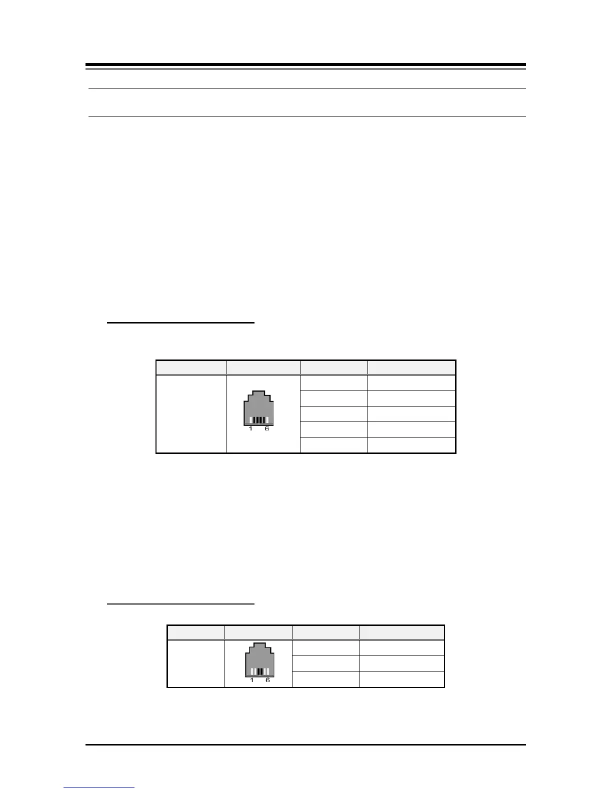
Modular Jack Pin Assignment
Table 7.3.1-1 LDP series (7000, 9000, 9200) Modular Jack Wiring
RJ11
1 N/A
2 Reserved
3,4 RING, TIP
5 Reserved
6 N/A
7.3.2 SLT Wiring
SLTs are wired to the center pair of the RJ11 jack, typically on the bottom or back of the
SLT. The wall outlet should be connected to an appropriate SLT port in the eMG80 system.
1. Wire the center pair of the wall outlet to the termination point using UTP cable.
2. Using the line cord provided with the SLT, connect the SLT to the wall outlet.
Table 7.3.2-1 SLT Modular Jack Wiring
Modular Jack Pin Assignment
 Loading...