iPECS eMG80
Hardware Description and Installation Manual Issue 1.3
69
6.4 Line and Station Modular Jack Wiring
The MBU and Interface boards determine the type and number of external network and
Station connections available. Section 4 provides details on each MBU and Interface boards.
The following provides wiring instructions for each of the Interface types.
All wiring of the modular jack terminations should be accomplished with 22 or 24 AWG twisted
pair wiring. Cabling for the RJ11 jacks should use a minimum of 2-pair wiring and the cabling
for the RJ45 should terminate all 4 pairs.
NOTE
In many cases, two interface circuits are terminated to a single modular jack. Thus,
carefully wire the jacks with the pin assignments shown otherwise, the interface circuits will
not operate properly.
6.4.1 CO Line Modular Jack Wiring
CO Line modular jacks are terminated with two (2) CO Lines to an RJ45 jack as shown in
the chart below. To wire the CO Line modular jacks,
1. Wire each CO Line modular jack to the termination point.
2. Tag the wiring for future maintenance.
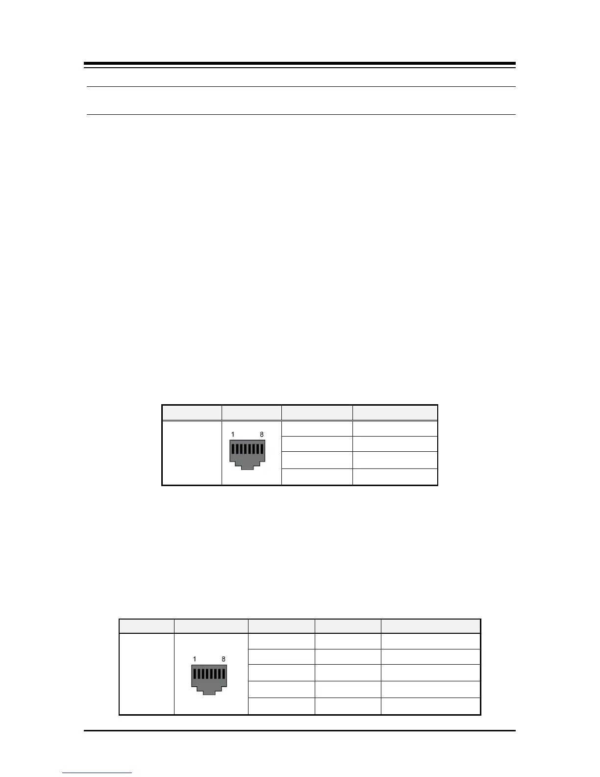
Table 6.4.1-1 Analog CO Line Modular Jack Wiring
Connector Pin-out Pin Number Signal Name
RJ45
1,2
CO1-R, CO1-T
3
Reserved
4,5
CO2-R, CO2-T
6,7,8
Reserved
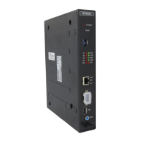
6.4.2 BRI Line Modular Jack Wiring
BRI Line modular jacks are terminated with one or two BRI lines (2B+D channels each) to
an RJ45 jack as shown in the chart below. To wire the BRI Line modular jack,
1. Wire each BRI Line modular jack to the termination point.
2. Tag the wiring for future maintenance.
Table 6.4.2-1 BRI Line Modular Jack Wiring