iPECS eMG80
Hardware Description and Installation Manual Issue 1.3
86
7.3.3 LIP Phone Wiring
iPECS eMG80 supports LIP Phone series. LIP-7008D and LIP-8004D have a single LAN
port that is wired to an Ethernet switch port. Generally all other LIP phone series shown
here have two (2) Ethernet ports, a LAN port and a PC port. The LAN port is connected to
an Ethernet switch port and the PC port is connected to the LAN port of a PC. The LIP
phones are wired to any 10/100 (or 1000) Base-T Ethernet switch port with access to a
VOIP channel. The LIP phones can be powered from a POE compatible Ethernet switch
port or using the AC/DC Adaptor-K.
Caution!
To power your phone, use either PoE or the AC adaptor, not both. Use the
Ericsson-LG Enterprise approved AC power adaptor only. The AC adaptor is
ordered separately.
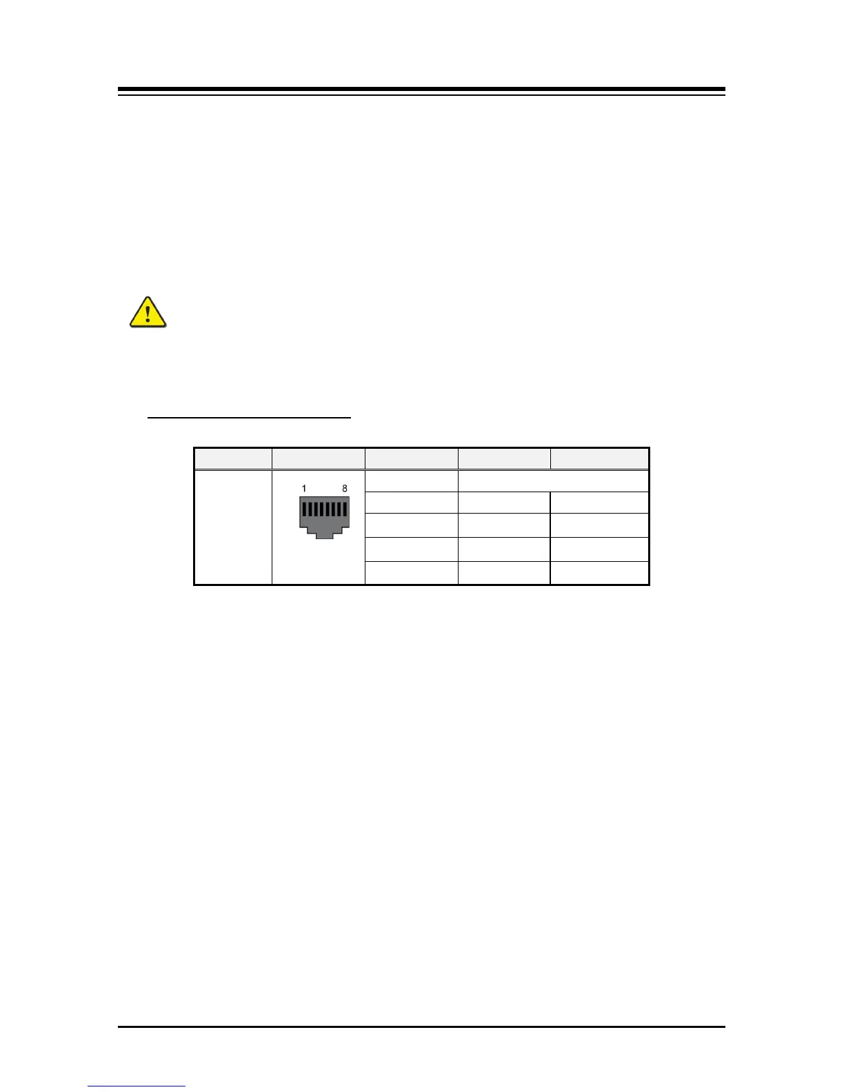
Table 7.3.3-1 LIP Phone Modular Jack Wiring
Modular Jack Pin Assignment
Connector Pin-out Pin Number Signal Name
Function
RJ45
4,5,7,8 Reserved
1 TX+ Transmit Data
2 TX- Transmit Data
3 RX- Receive Data
6 RX+ Receive Data
1. Using the above wiring chart, wire the RX and TX pins from the RJ45 Wall outlet, or
equal, for the IP Phone to the appropriate Ethernet switch termination point using
Cat 5 or, for 1000 Base-T Cat 5e UTP cable. The maximum wire length between the
IP Phone and the Ethernet switch port is 100 meters or 328 feet.
2. Use the RJ45 terminated cable provided with the phone to connect the IP Phone
LAN port to the Wall outlet.
3. Connect the PC port to a PC LAN port using a CAT 5 cable terminated on each end
with an RJ45 connector.
4. If not using a POE switch port, connect the DC connector of an AC Adaptor-K to the
DC input on the bottom of the IP Phone and plug the AC plug of the AC adaptor in to
a 100-240 VAC outlet.
Once the LIP phone powers up, it will attempt to register with the eMG80. From default, the
LIP phone should complete the registration successfully. If not, the phone will display the
“No Response” message shown below.
NO RESPONSE FROM MFIM [L]
SET[*] – RETRY[#]
This indicates the LIP phone needs to be configured for the local network environment. To
configure the phone, perform the following steps.
1. Press ‘*’ to set the network configuration
2. Enter the password, 147*.
 Loading...