iPECS eMG80
Hardware Description and Installation Manual Issue 1.3
70
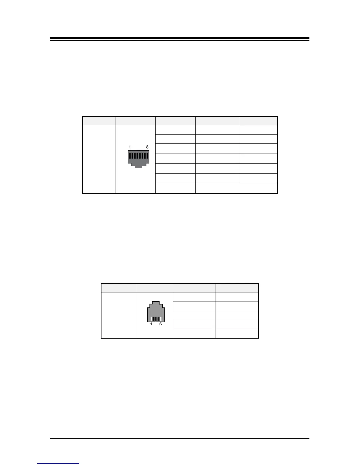
6.4.3 PRI Line Modular Jack Wiring
The PRI Line modular jack is terminated with one PRI line circuit to an RJ45 jack as shown
in the chart below. To wire the PRI Line modular jack,
1. Wire each PRI Line modular jack to the termination point.
2. Tag the wiring for future maintenance.
Table 6.4.3-1 PRI Line Modular Jack Wiring
RJ45
1
RX-T / TX-T TE / NT
2
RX-R / TX-R TE / NT
4
TX-T / RX-T TE / NT
5
TX-R /RX-R TE / NT
3
N/A
6
N/A
7, 8
N/A
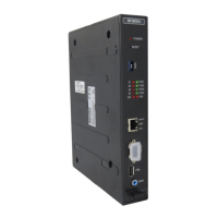
6.4.4 Digital Station Modular Jack Wiring
Digital Station modular jacks are terminated with one Digital station circuit to an RJ11 jack
as shown in the chart below. To wire the Digital Station modular jack,
1. Wire each Digital Station modular jack to the termination point.
2. Tag the wiring for future maintenance.
Table 6.4.4-1 Digital Station Modular Jack Wiring