iPECS eMG80
Hardware Description and Installation Manual Issue 1.3
57
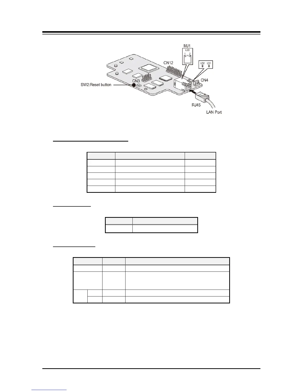
Figure 4.8.1-1 VVMU
Table 4.8.1-2 Connector and Modular Jack Function
Connector and Modular jack
CN1 Connection to CN3 of the MBU 32 Pins
CN3 CPLD JTAG for development 10 Pins
CN12 CPU JTAG for development 20 Pins
CN4 Maintenance Serial port 4 Pins
MJ1 LAN Port RJ45
Table 4.8.1-3 VVMU Push Button Reset SW2
Switch setting
SW2 Reset push button
Table 4.8.1-4 VVMU LED Indication
LED Indications
LD1 Blue Flash 300ms ON and OFF, normal operation
LD2 Blue Channel in use status
ON – a VoIP or VM channel in use
OFF – all VoIP and VM channels idle
MJ1 LD1 Link/Act ON – Link, Blink – Data Transfer
LD2 Speed ON – 100Mbps, OFF – 10Mbps