Applications Guide
148
Rev. L6 Feb 2017 Modline 5
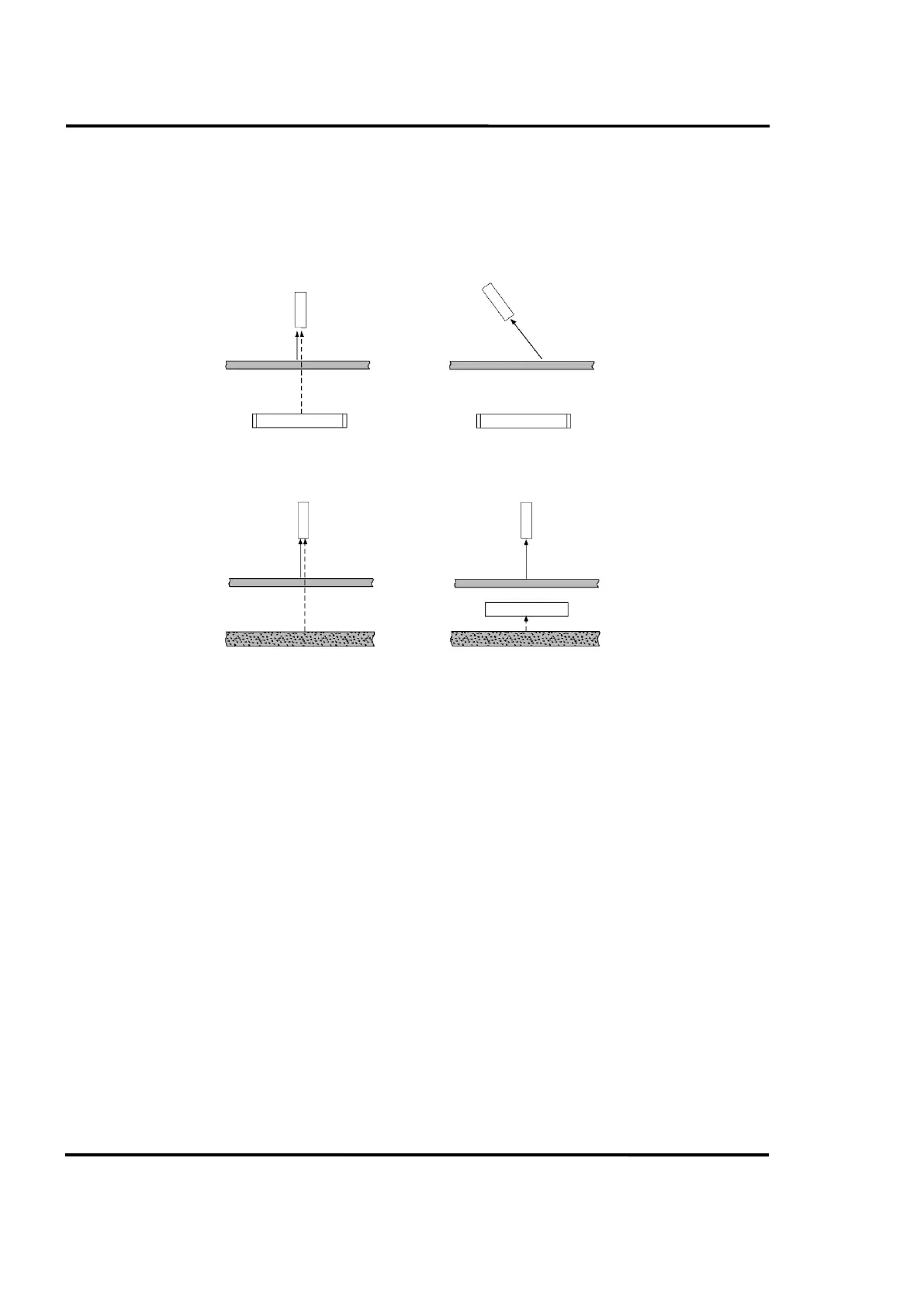
target, by selecting a different measurement point away from the background source, or by inserting a
cooled shield behind the workpiece. See Figure 87 for examples. These considerations apply to all Sensor
series.
Figure 87: Solving Common Transmission Problems
8.8.4 Transmission Path Effects
Materials in the transmission path may absorb infrared radiation, reducing the amount of radiant
energy an instrument receives. This is less of a problem for Series 5R Ratio Sensors, as long as the
radiance at both detected wavelengths is reduced equally. For any other Sensor Series, a poor
transmission path causes the indicated temperature to be lower than the target's true temperature. These
problems may be minimized by keeping the System's optical components clean, and by selecting a sight
path for which the entire optical cone between the target and the instrument is free of solid objects, dust,
smoke, and evaporates. Sight tubes, shown in Figure 88 can be used for this purpose. For information
on the use of windows, refer to Section 8.10 Use of Windows, page 150.
8.8.5 Reflectance Effects
If the target has some reflectance, it acts as a mirror and reflects infrared energy generated by other
sources (e.g. a furnace wall or heating element). If the Sensor picks up the reflection, measurement errors
will result. Reflectance depends on the target material and the condition of its surface. Flat, smooth
surfaces tend to have larger reflectance values than roughened surfaces of the same material.
Reflectance problems may be reduced by changing the viewing angle so that the reflection is not picked
up by the Sensor, or by the use of sight tubes or some other form of shielding. (See Figure 88 examples.)
These considerations apply to all Sensor Series.