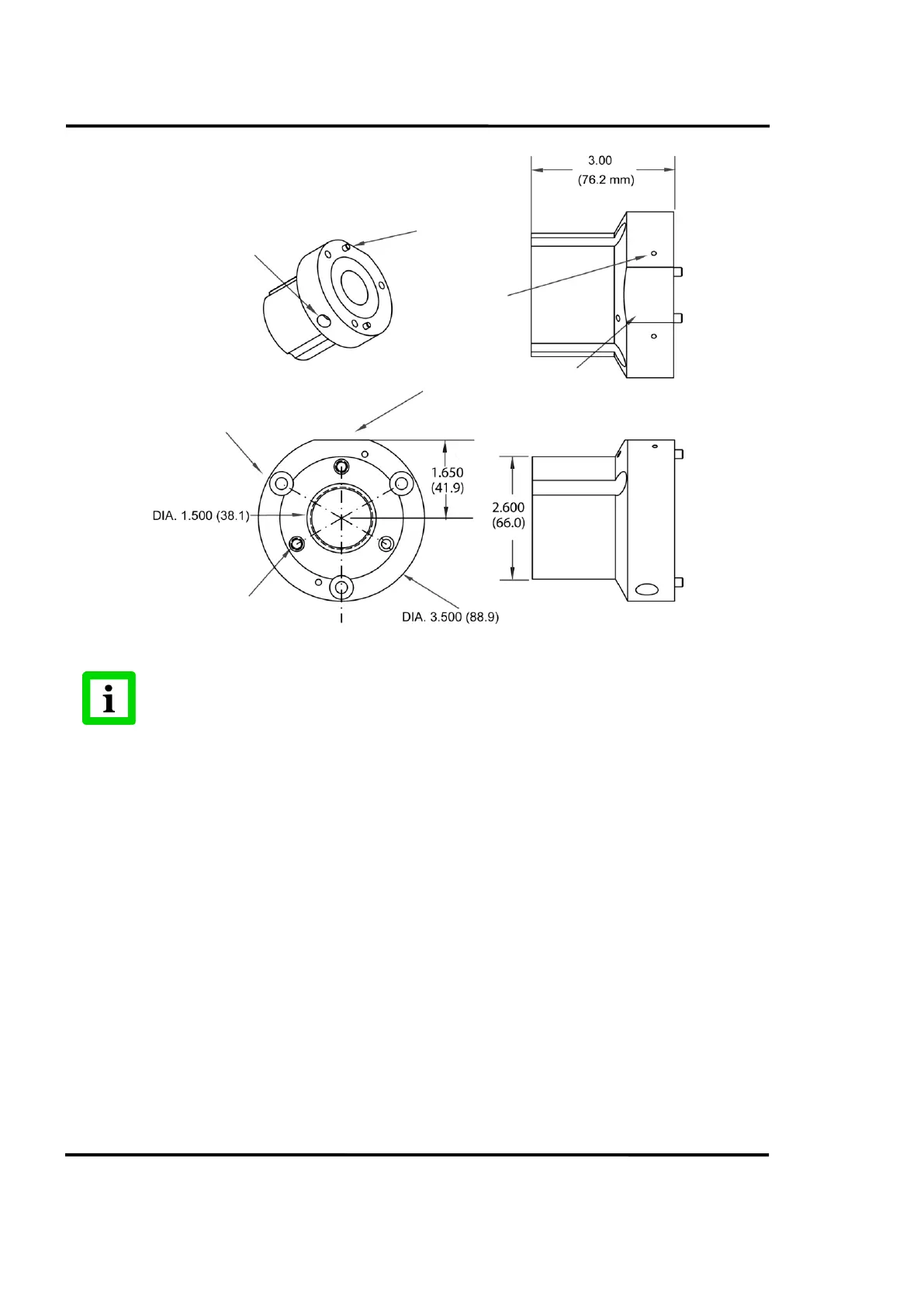
EasyManua.ls Logo

ircon Modline 5 - MFL - Mounting Flange Large Description and Dimensions

ircon Modline 5
156 pages
Print Icon
To Next Page IconTo Next Page
To Previous Page IconTo Previous Page
Loading...
Sensor Installation
40
Rev. L6 Feb 2017 Modline 5
Figure 26: APA Dimensions
Dimensions are in inches and (millimeters). Do not scale.
3.9.4 MFL Mounting Flange Large Description and Dimensions
The larger of the two mounting flange accessories, the MFL has the bolt circle pattern that matches many
of IRCON’s other products and accessories. It provides a simple means of replacing older instruments
and using existing accessories. See Section 3.12 for Other Accessories.
The MFL is mated to the Sensor by attaching it to the threaded holes in the front of the UAA, APA and
WJA accessories. Inner and outer groups of three through holes are used for attachment. These holes
are covered by a metal gasket.
Three Counterbore
Holes for M6 Sockethead Cap Screws
For assembling to UAA or WJA
1/4 -20 NPT Air Inlet
Locating PINs 2 Places
Drain Holes
2 Places
Flat surface align with flat
surfaces on other Accessories
Three M6 tapped Holes for
mounting MFS or MFL Flanges

Table of Contents

Other manuals for ircon Modline 5

Related product manuals