Applications Guide
150
Rev. L6 Feb 2017 Modline 5
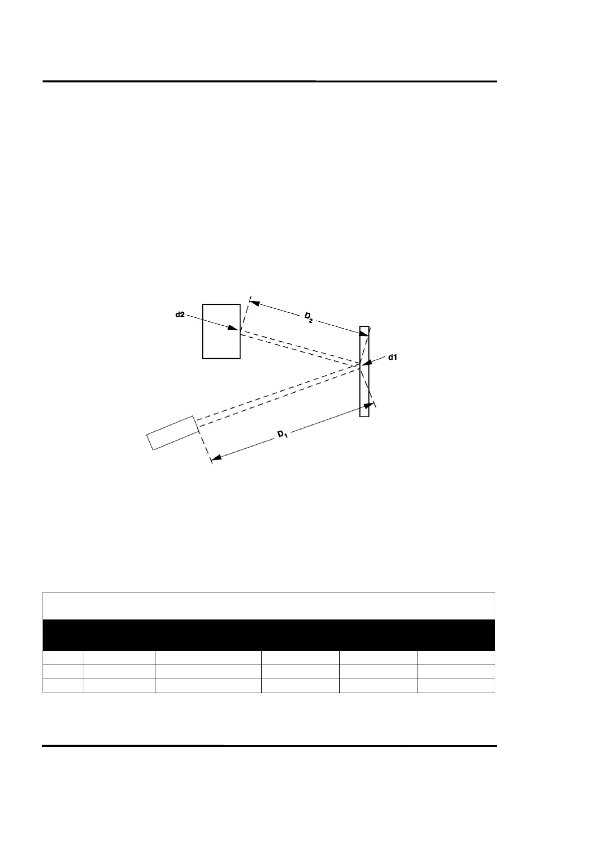
As indicated in Figure 89, the Cone of Vision extends from Sensor-to-mirror-to-target. The mirror
effectively bends the cone but does not change its shape.
There are two spot sizes to consider in Figure 89: spot size d1 at the mirror surface (distance D1) and
spot size d2 at the target surface (distance D2). Mirror and target areas must be at least twice the cone
diameter at their respective distances.
The mirror must be positioned (and angled) so that the axis of the reflected target image coincides with
the optical axis of the Sensor. You should be able to accomplish the alignment without difficulty by
sighting through the viewing telescope.
Be sure to lock the mirror firmly in position, and check the alignment on a regular basis. Also, inspect
and clean the mirror (in manner recommended by the manufacturer) as part of your regular
maintenance routine. If you have any trouble in obtaining an appropriate mirror or in erecting your
system, please contact IRCON for recommendations.
Figure 89: Effect of Using a Mirror on Optical Cone
8.10 Use of Windows
To view an object in an inert atmosphere or vacuum chamber, you must use an infrared transmitting
window. Selection of an appropriate window material will depend on the Sensor's spectral response.
Some suggested window materials for various Modline 5 Sensor Series are listed in the Window
Selection Guide Table 21.