Table: 14
D. Select Next Step. If the preparation is for a POI Box, see the separate POI manual for cable
preparation and installation instructions. If the preparation is for a Terminal Strip Plate, pull back
and comb out the exposed shield. Preparation is now complete. Route and install the
interconnecting cable. Refer to Section 4.6 Terminal Strip Plate – Sensor Interconnecting Cable
Installation, page 68.
4.5.2 Interconnecting Cable Assembly Continuity Check
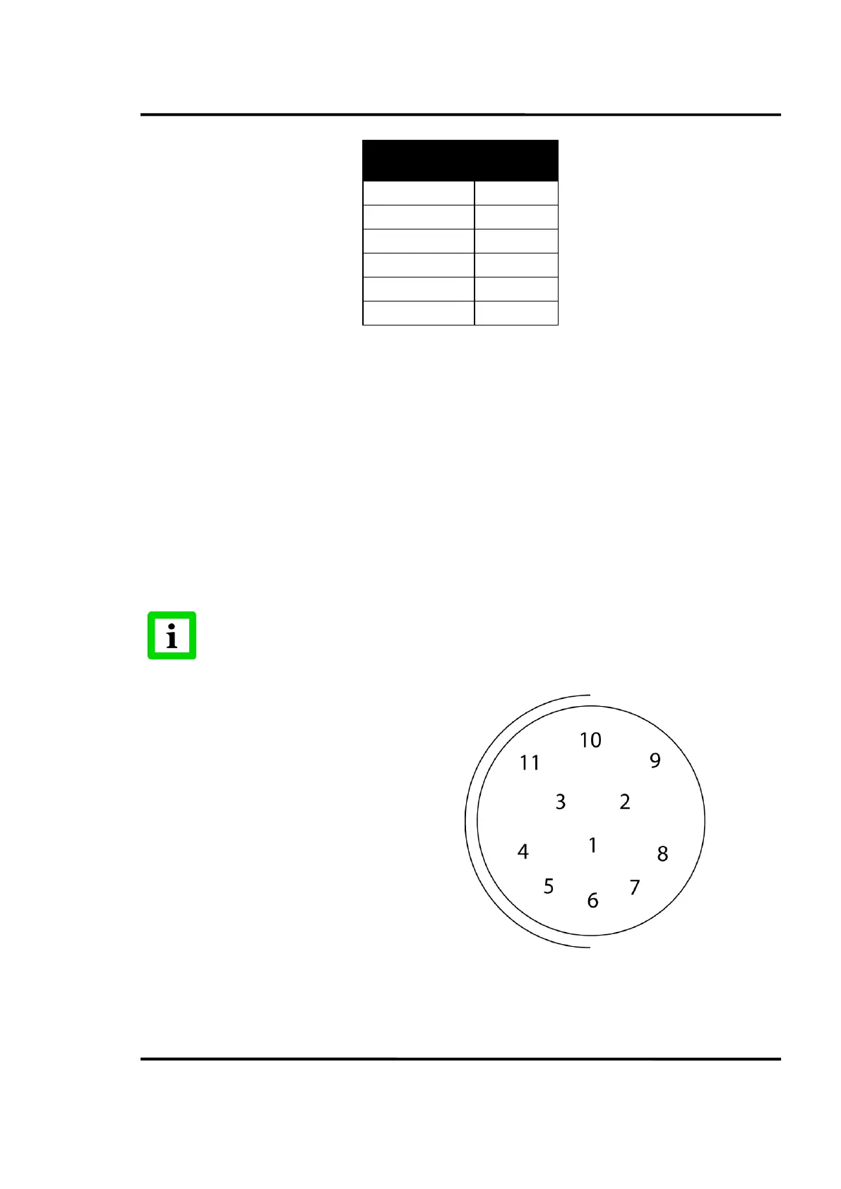
If desired, a continuity check of the cable can be made. The table below identifies the receptacle pin and
the color coded wire connected to the pin. The illustration below identifies the pin locations on
the cable plug end.