Sensor Installation
Modline 5
Rev. L6 Feb 2017 55
Figure 45: UAA
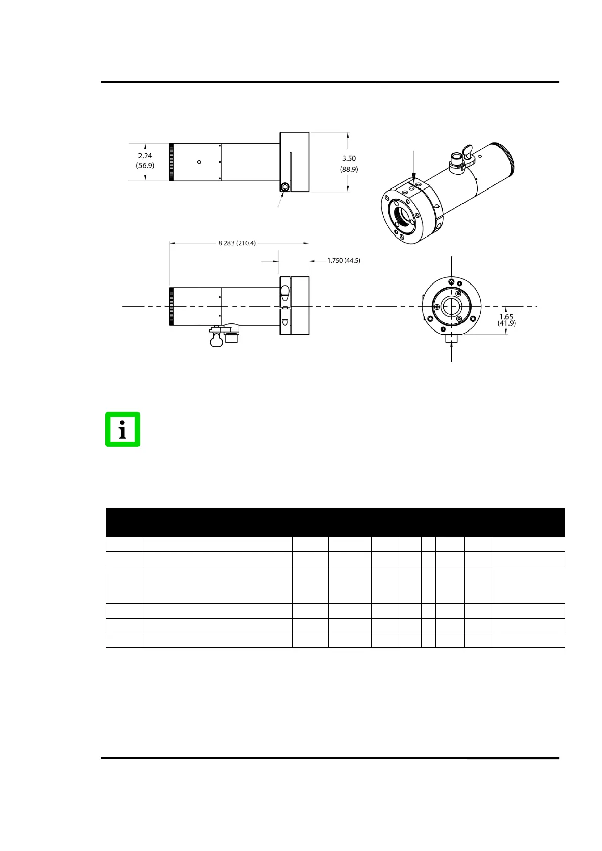
3.11.2 Installation Drawing for the RAM – Right Angle Mount
Required Accessories. See Individual
Accessory Descriptions and Dimensions.
Right Angle Mount with Air Purge
Right Angle Mount with Large Flange.
This group requires an ESA for
clearing the RAM
Right Angle Mount with Large Flange
Right Angle Mount with Air Purge
Right Angle Mount with Air Purge
DWD is Dirty Window Detector Option. Refer to notes with grouping table in Section 3.10 Accessory Combinations with
Break-out Drawings, page 50. The ESA adds 1.82 in. (46.2 mm) to length of the assembled group.
Table 9: Recommended Accessory Groupings RAM
Dimensions are in inches and (millimeters). Do not scale.
Group 1 shown (UAA and Sensor).
See UAA description and Dimensions.
Sensor Front inserted Level with UAA Front.
¼ hex Head Screws (3)
with flat and lock washers
supplied for mounting.
M8 X 30 mm Socket Head Cup Screw
supplied for clamping Sensor.