Sensor Installation
56
Rev. L6 Feb 2017 Modline 5
When using the MFL (Group 8) or APA (Group 7, 9, 10), assemble these accessories
to the UAA and RAM first. Place Sensor fully into assembly and rotate Sensor to
desired position to clear table. Tighten clamping screw.
Sensor front surface will be positioned at the back end of the APA or MFL. To determine working
distance (D) for spot size formula d=D/F, measure or calculate from that point.
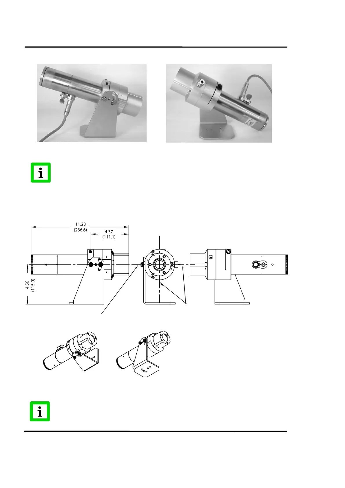
Figure 48: Group 7 shown (UAA RAM and APA).
Dimensions are in inches and (millimeters). Do not scale.
See individual Accessory drawings.
Optical Axis Coincident with Axis of Rotation