Acceptance and Installation
Copyright © ITECH Electronic Co., Ltd. 3
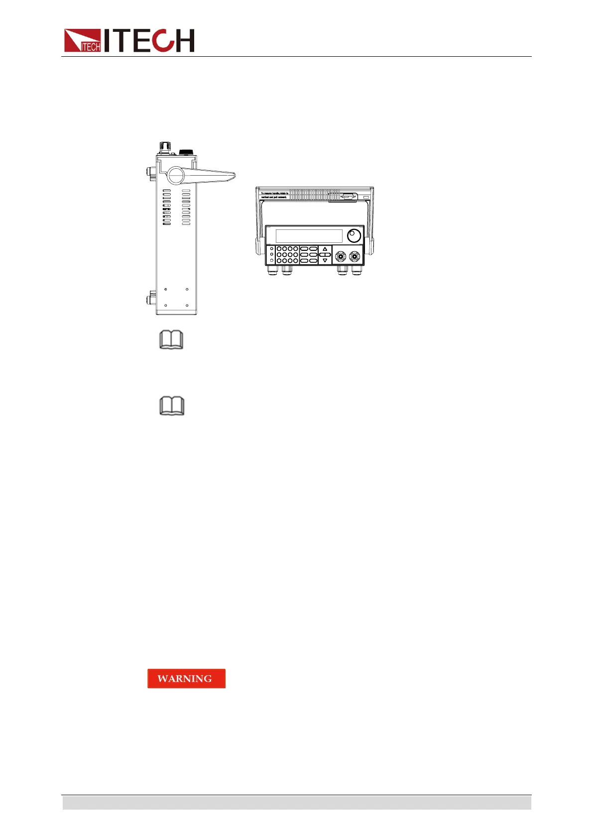
1.4 Disassembly of load handle
Please disassemble the load handle before installing equipment on the support.
Disassembly steps:
1. Adjust the handle to the position as shown in the figure below.
NOTE
To easily disassemble handle, align the locking mouth and locking device, which is
between the handle and the instrument.
2. Align the locking mouth, and pull out the handle towards two sides.
NOTE
Do not use too much force and mind your hands during disassembly of load handle.
1.5 Installation of support
IT8800 Series load can be mounted on a standard 19” rack. ITECH provides
user with IT-E151/IT-E151A rack, as an optional mount kit. The detailed
operation please refer to the User Manual of your mount kit.
1.6 Connecting the DUT
Before connecting the DUT
Test lines are not standard accessories of the instrument. Please select
optional red and black test lines for individual sales based on the maximum
current value. For specifications of test lines and maximum current values, refer
to “Specifications of Red and Black Test Lines” in “Appendix”.
Before connecting DUT, be sure to switch off the power supply of
the test loop in order to avoid electric shock.
To avoid electrical shock, before testing, please make sure the
rating values of the testing lines, and do not measure the current that
higher than the rating value.
Always use test lines provided by ITECH to connect the
equipment. If test lines from other factories are used, please check