Acceptance and Installation
Copyright © ITECH Electronic Co., Ltd. 4
that the test line can withstand maximum current.
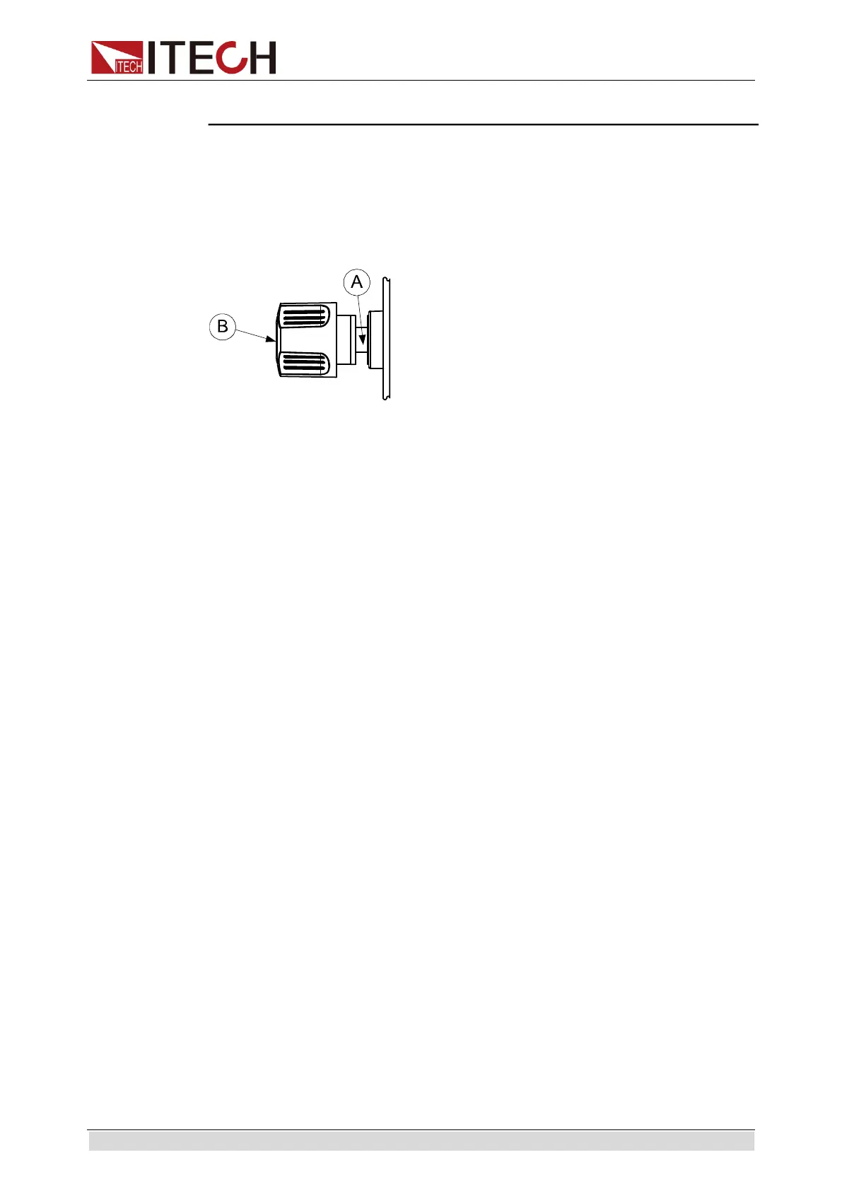
Introduction of Binding Posts
The maximum rated current of the terminal at position (A) is the maximum rated
input current of the instrument. Securely fasten all wires by hand-tightening the
binding posts. You can also insert standard banana plugs into the front of the
connectors as shown in (B), and the maximum rated current at (B) is 10 A.
Connecting the DUT
Test line connection is given below taking local measurement as example. For
details of local and remote measurements, refer to “Terminal function of rear
board”.
1. Before connecting the test lines, be sure that the instrument Power is in Off
position.
2. Unscrew the screws of the input terminals and connect the red and black
test lines to the input terminals. Re-tighten the screws.
When maximum current that one test line can withstand fails to meet the
current rated current, use several pieces of red and black test lines. For
example, the maximum current is 1,200A, then 4 pieces of 360A red and
black lines are required.
3. Directly connect the other end of the red and black lines to the DUT
terminal.
1.7 Connecting the Power Line
Connect power line of standard accessories and ensure that the electronic load
is under normal power supply.
AC power input level
Working voltage of IT8811/IT8812/IT8812B/IT8812C includes 110V and
220V(which can be selected by the switch on rear board of load).
AC power input level:
Option Opt.1: 220Vac 50Hz/60Hz
Option Opt.2: 110Vac 50Hz/60Hz
Categories of power lines
Please select appropriate power lines appropriate to local voltage based on the
specifications of power lines below. If purchased model fails to meet local
voltage requirements, please contact distributor or factory for change.