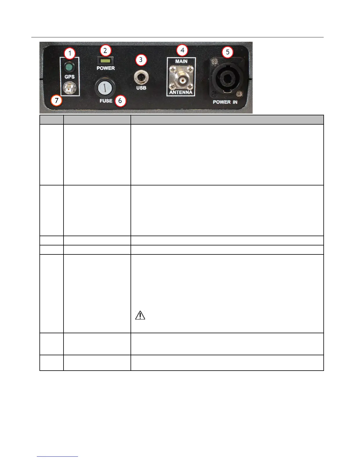
ID Connector Description
1 GPS LED indicator
An LED that indicates the status of the GPS antenna.
•
A lit LED indicates that the GPS antenna is operating properly.
• An unlit LED indicates that the GPS antenna is not operating
properly and should be serviced.
For more information, see Connecting the GPS and Data Cables
on page 36.
2 Power indicator
An LED that turns on when the MC3Lite is receiving power.
• A solid LED indicates that the power is on and the radio is
connected to the Mobile Collection computer via the USB cable.
• A flashing LED indicates the power is on, but the radio is not
connected to the Mobile Collection computer via the USB cable.
3 USB Connects the Mobile Collection computer to the MC3Lite radio.
4 Main antenna Connector for the roof-mounted omni-directional antenna cable.
5 Vehicle power
Input that receives the connector running to the vehicle power
source to provide power to the MC3Lite.
In addition to wiring the power cable directly to the vehicle, a 12V
auxiliary power cable is available. Itron recommends the use of the
permanent solution for better power sourcing.
Caution:
When using the auxiliary power cable, always
disconnect this cable from the power source when not in
use. Failure to do so could result in a dead vehicle battery.
6 Fuse holder
Holder that accepts standard automotive 12V (15amp) AGC fuses
(1 included) to protect internal circuitry from power surges by the
vehicle.
7
GPS antenna
connector
Connects the MC3Lite to the roof-mounted GPS antenna.
Connecting the Power Cables
Power to the Mobile Collection components is distributed through the junction box on the
side of the sled. There are three power cables that must be connected.
Installing MC3Lite Components
MC3Lite Vehicle Preparation and Hardware Installation Guide TDC-1548-002 31
Proprietary and Confidential