28
Electrical Installation and Wiring
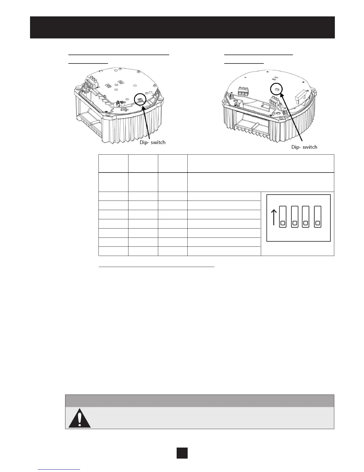
HVB 1202 / 1203, HVB 3403 / 3405 HVB 3407 / 3410 / 3415
Basic Inverter Basic Inverter
Switch Switch Switch
Address
1 2 3
OFF OFF OFF
Address 1 (default setting)
(Required setting for the use with control card)
OFF OFF ON Address 2
OFF ON OFF Address 3
OFF ON ON Address 4
ON OFF OFF Address 5
ON OFF ON Address 6
ON ON OFF Address 7
ON ON ON Address 8
Switch 4 not used!
Setting the correct address on Basic drives:
• The HYDROVAR must be disconnected from power supply for at least 5 minutes
before removing the top cover!
• Use the dip-switch on the power unit. (See picture above!)
• Set the desired address for each HYDROVAR
E.g. Address 4 -> switch 1 is set to OFF
switch 2 and 3 are set to ON
• Mount the cover on the HYDROVAR and tighten the four fastening screws
• Reconnect HYDROVAR to power supply
8.4.4 Control Terminals
All control wires connected to the control-unit must be screened (See section 8.2 for recommend-
ed wire types).
External voltage free contacts must be suitable for switching <10 VDC.
Note
If unscreened control wires are used, signal interference may occur and could
interfere with the function of the HYDROVAR.
Do not connect the control card ground to other voltage potentials. All electronic ground termi-
nals and GND of the RS 485-interface are connected internally.
ON
1 2 3 4