57
Programming
0435
0435 SENS 1 CAL X
Sensor 1 upper range value calibration
0% = actual value
Possible settings: - 10% up to +10%
To set the calibration for the upper range value of sensor 1. After setting the dimension unit and sensor
range, the upper range value can be adjusted between -10 and +10%.
0440
0440 SENS 2 CAL 0
Sensor 2 zero point calibration
0% = actual value
Possible settings: - 10% up to +10%
Zero point calibration for Sensor 2, for explanation see Parameter 0430.
0445
0445 SENS 2 CAL X
Sensor 2 upper range value calibration
0% = actual value
Possible settings: - 10% up to +10%
Upper range calibrations for Sensor 2, for explanation see Parameter 0435.
0500
0500 SUBMENU
SEQUENCE CNTR.
This submenu defines parameters for multi-pump systems.
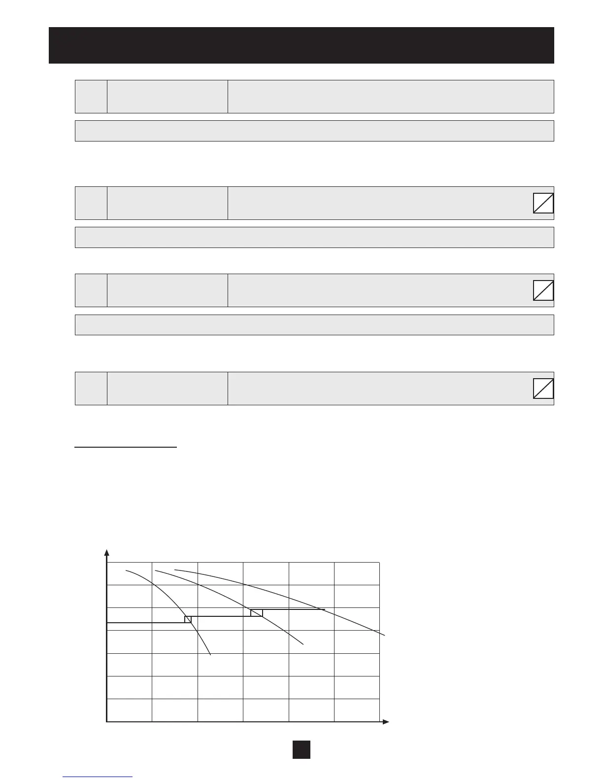
Application Example:
1) Lead pump reaches its ENABLE FREQUENCY [0515]
2) Actual value falls and reaches the cut in-value of the 1st assist pump Cut in-value = REQUIRED VALUE
[02] – ACT. VAL. DEC. [0510] → the 1st assist pump is switched on automatically
3) After the start up the new required value is calculated in the following way:
NEW REQUIRED VALUE = REQ. VAL. [02] – ACT. VAL. DEC [0510] + ACT. VAL. INC. [0505].
The new required value is shown in the main menu as parameter EFF. REQ. VAL. [03].
S
S
S
H
Q
0
0
P 1 P 1 +2 P 1 +2+3