5-26 4181384 First Edition
HYDROSTATIC POWER TRAIN
5
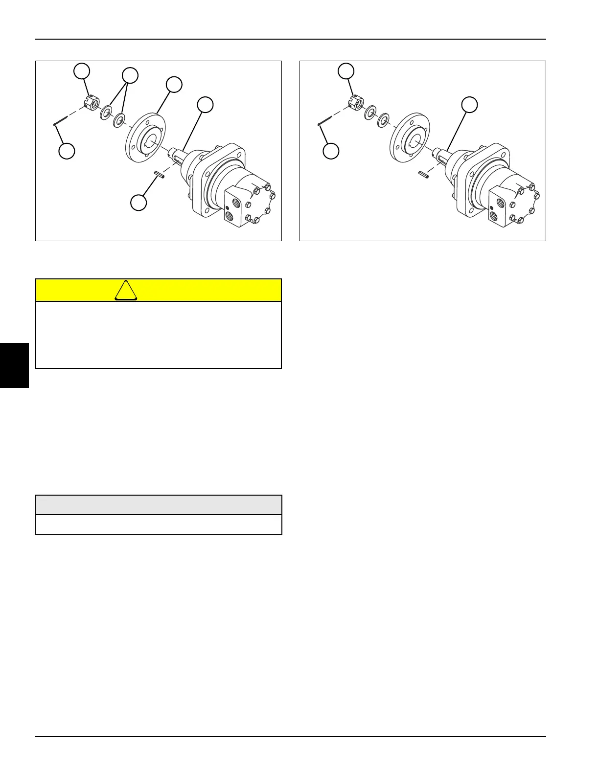
Figure 5-29
8. Remove cotter pin (18).
!
CAUTION
9. Loosen, but do not remove, the castle nut (13).
10. Loosen the wheel flange (15) from the motor shaft
(16) using a puller.
11. Remove the castle nut (13), two flat washers (14),
and wheel flange (15) from the motor shaft (16).
12. Remove key (17) from the motor shaft (16).
Installation Notes
Figure 5-30
• Install the front wheel motor by reversing the order of
removal.
• Apply anti-seize compound to the motor shaft
threads. Be careful not to apply anti-seize compound
to the motor shaft (20).
• Tighten castle nut (19) to 332 ± 7 lb-ft
(450 ± 10 N·m).
• Install a new cotter pin (21) in the castle nut (19) and
motor shaft (20).
• Check hydraulic oil level. Add oil as needed. (Refer to
“Safety, Operation, and Maintenance Manual” for the
correct oil specifications.)
The wheel hub may move unexpectedly when
using a puller. To prevent injury and/or property
damage, do not remove the castle nut until the
wheel hub has been loosened from the wheel
motor shaft.
Required Materials
Anti-Seize Compound
TN1287
13
14
15
16
17
18
TN1287
19
20
21