HYDROSTATIC POWER TRAIN
4181384 First Edition 5-35
5
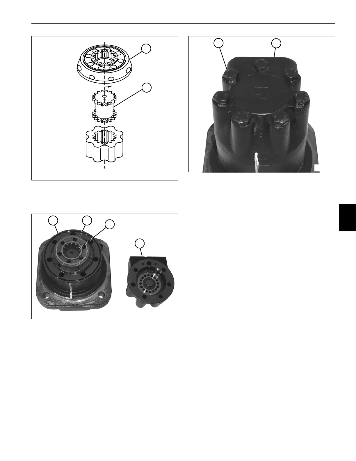
Figure 5-59: Correct Motor Timing
26. Align mark on valve drive (43) with a hole in the outer
rim of disk valve (42).
Figure 5-60
27. Install the disk valve (42) on the valve drive (43) and
valve plate (44).
28. Install the end cover assembly (45) over the disk
valve (42) and valve plate (44).
Figure 5-61
29. Install seven screws (46) in the end cover (47).
Tighten screws using an alternating pattern to 52 lb-ft
(70 N·m).
TN1366
~
43
42
TN1311
44 42
45
43
TN1310
46
47