5-34 4181384 First Edition
HYDROSTATIC POWER TRAIN
5
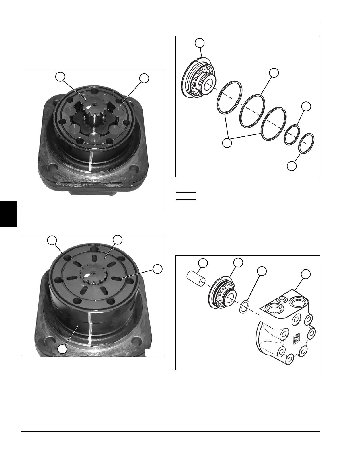
17. Mark the bottom of a spline on both ends of the valve
drive (26).
18. Line up mark on gear wheel set rotor (27) with marks
on valve drive (26).
Figure 5-55
19. Install the valve drive (26) in the gear wheel set (28).
l
Figure 5-56
20. Install the valve plate (30) on the gear wheel set (32)
with the oval ports (31) facing away from the gear
wheel set.
21. Install an O-ring (29) on the valve plate (30).
Figure 5-57
NOTE
Install the backing rings in the same locations as record
during removal.
22. Install O-ring (34) and two backing rings (37) on the
balance plate (33).
23. Install O-ring (35) and backing ring (36) on the
balance plate (33).
Figure 5-58
24. Install spring washers (40) and balance plate (39) in
the end cover (41).
25. Apply a thin film of petroleum jelly to spacer (38), and
install spacer in the end cover assembly (41).
TN1313
~
28
26
TN1312
29
30
~
~
32
31
TN1343
33
34
35
36
37
TN1342
38
39
41
40