HYDRAULICS
4181384 First Edition 6-45
6
Disassembly and Assembly
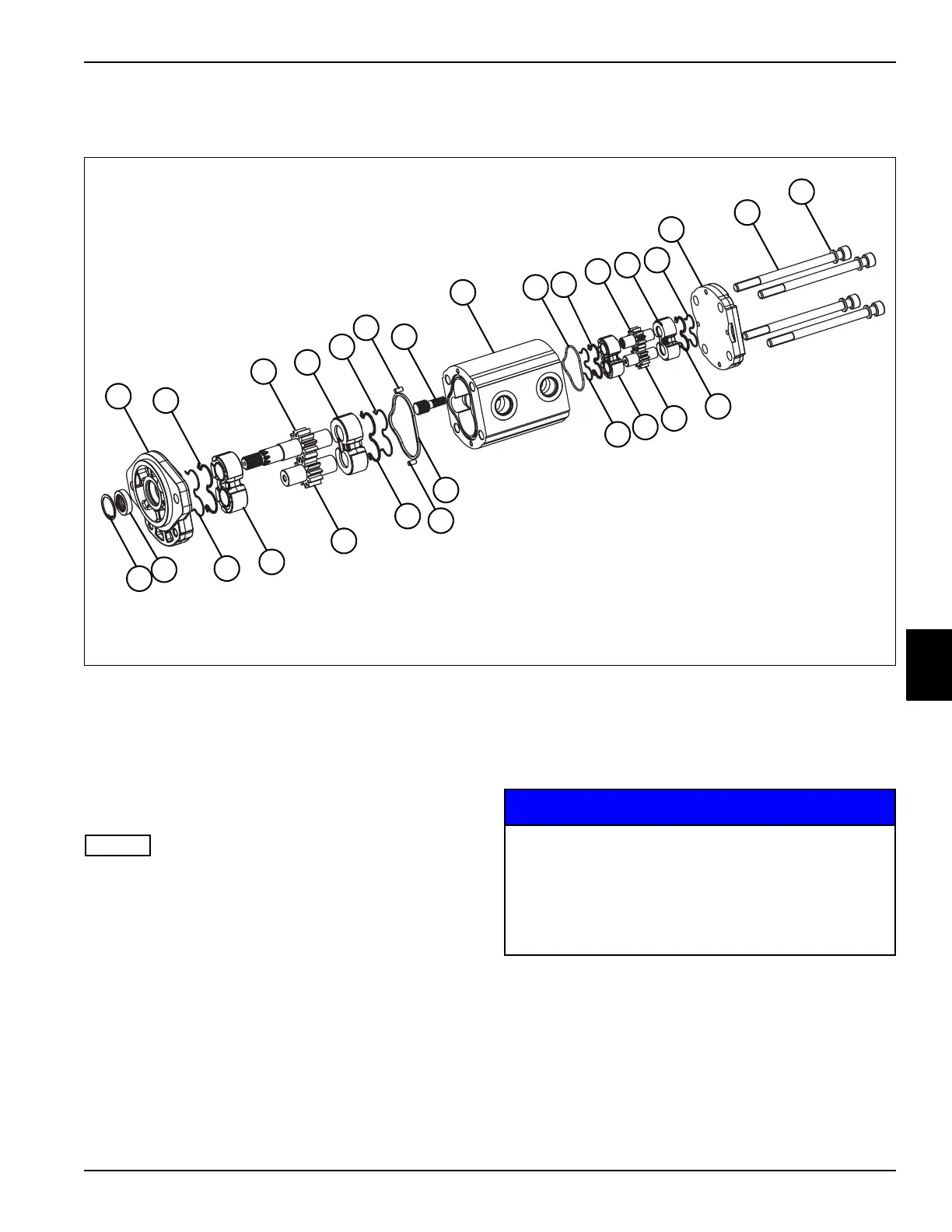
See Figure 6-39.
Figure 6-39
1. Park the mower safely. (See “Park Mower Safely” on
page 1-7.)
NOTES
Never pry components apart. Use a soft face hammer to
gently tap housing and shaft to separate pump body.
Scribe or mark pump body and end covers before
disassembly to ease assembly.
2. Remove cap screws and disassemble pump one
section at a time. Before removing drive shaft and
driven gear shafts, mark a line across meshing gear
teeth to ensure that shafts are reassembled in the
same position.
3. Remove parts and place in assembly order on a
clean work area.
4. Discard seals as they are removed.
NOTICE
5. Clean all parts using clean solvent, and dry using
compressed air.
6. Inspect all parts for wear or damage. Replace parts
as needed.
1 Front Cover 5 Backup Ring (4) 9 O-Ring (2) 13 Washer (4)
2 Seal (4) 6 Dowel Pin (2) 10 Drive Gear 14 Driven Gear Shaft
3 Drive Shaft 7 Hub 11 Twin Rear Cover 15 Shaft Seal
4 Thrust Plate (4) 8 Body 12 Screw (4) 16 Ring
TN1232
1
2
3
4
5
7
9
2
10
4
5
11
12
13
15
16
5
4
14
2
9
8
5
4
14
2
6
6
It is important that all components are absolutely
clean, as contamination can result in serious
damage and/or improper operation.
Never use shop towels or rags to dry parts after
cleaning, as lint may clog passages. Dry parts
using compressed air.