HYDRAULICS
4181384 First Edition 6-49
6
Disassembly, Inspection, and Assembly
See Figure 6-44.
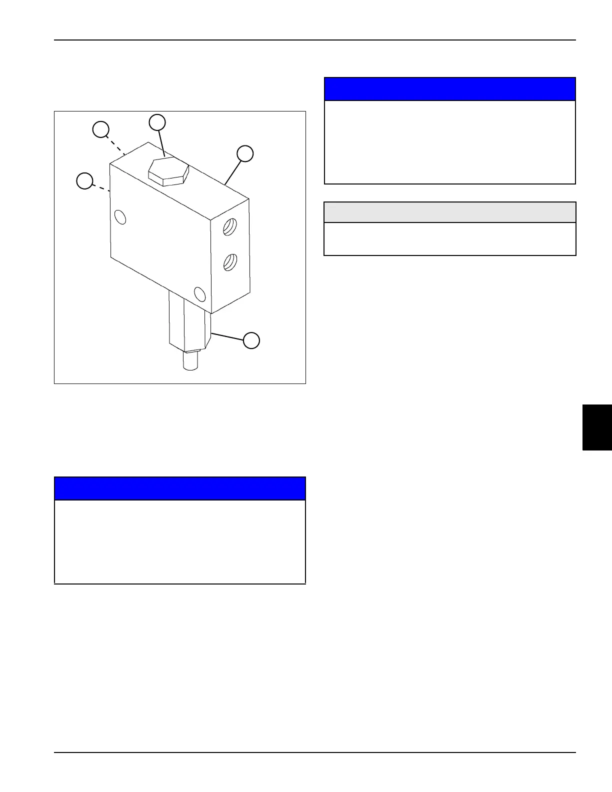
Figure 6-44
1. Remove, inspect, and replace flushing valve
components as needed.
NOTICE
2. Clean all parts using clean solvent, and dry using
compressed air.
3. Inspect all parts for wear or damage. Replace parts
as needed.
Assembly Notes
NOTICE
• Assemble flushing valve by reversing the order of
removal.
• Lubricate all O-rings prior to assembly.
• Tighten the check valve (2) to 37 lb-ft (50 N·m).
• Tighten sequence valve (4) to 37 lb-ft (50 N·m).
• Tighten M5 x 1.00 diameter orifice plug (5) to 2 lb-ft
(27 lb-in.) (3 N·m).
• Tighten M5 x 0.50 diameter orifice plug (1) to 1.7 lb-ft
(20 lb-in.) (2.5 N·m).
1 Orifice Plug 4 Sequence Valve
2 Check Valve 5 Orifice Plug
3 Flushing Valve Block
It is important that all components are absolutely
clean, as contamination can result in serious
damage and/or improper operation.
Never use shop towels or rags to dry parts after
cleaning, as lint may clog passages. Dry parts
using compressed air.
TN1336
2
4
1
5
3
It is important that all components are absolutely
clean, as contamination can result in serious
damage and/or improper operation.
Never use shop towels or rags to dry parts after
cleaning, as lint may clog passages. Dry parts
using compressed air.
Required Materials
Seal Kit, Sequence Valve (Jacobsen P/N 4137262)
Seal Kit, Check Valve (Jacobsen P/N 4137263)