8-32 4181384 First Edition
CUTTING UNITS
8
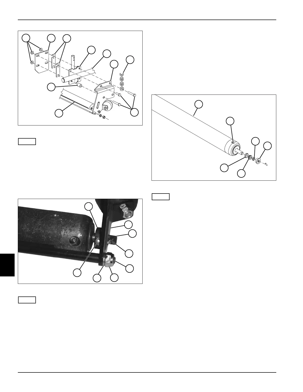
Figure 8-19
NOTE
Chain (7) applies to outer side of the front cutting units
only.
4. Remove four screws (8) and nuts (1), two spacers
(10), and six shims (3) from deck frame weldments
on each side of deck frame (5).
5. Remove deck weldments (2, 4, and 6) and roller
assembly (9) from deck frame (5).
Figure 8-20
NOTE
Steps 6 through 9 apply to both sides of the roller
assembly.
6. Loosen set screw (18) from collar (11) on roller shaft
(13).
7. Remove pin (14) from roller shaft (13).
8. Remove lock nut (16) and washer (17) from scraper
shaft (15).
9. Remove weldment (12) from roller shaft (13) and
scraper shaft (15).
Installation Note
Install the roller by reversing the order of removal.
Disassembly, Inspection, and Assembly
See Figure 8-21.
1. Park the mower safely. (See “Park Mower Safely” on
page 1-7.)
2. Remove deck roller from cutting unit. (See “Deck
Roller” on page 8-31.)
Figure 8-21
NOTE
Do not remove bearing cone (6) unless it is necessary to
replace the bearing (5). Always replace the bearing and
bearing cone as a set.
3. Remove seal (4), lock nut (3), and bearing (5) and
bearing cone (6) from both ends of roller (1).
4. Inspect roller, shaft, bearings, and bearing cups for
wear or damage. Replace as necessary.
Assembly Notes
• Assemble the deck roller by reversing the order of
disassembly.
• Apply grease to grease fitting (2) at both ends of
roller (1). (Refer to “Safety, Operation, and
Maintenance Manual” for grease specifications.)
TN1197a
10
5
3
8
1
2
4
7
6
9
TN1327
17
18
16
15
14
13
11
12
TN1197
1
4
5
3
6
2