ACCESSORIES AND MISCELLANEOUS REPAIR
4181384 First Edition 9-11
9
Disassembly and Assembly
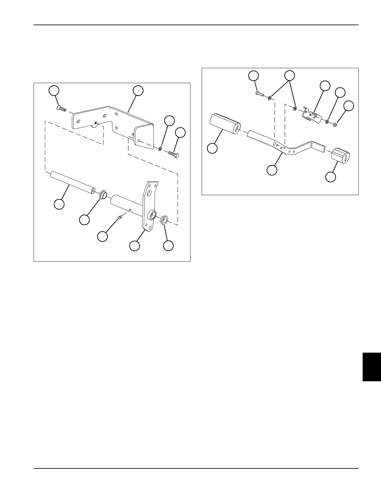
Pedal Bracket Assembly
See Figure 9-22.
Figure 9-22
Assembly Notes
• Apply grease to flanged bushings (5) before
installing. (Refer to “Safety, Operation, and
Maintenance Manual” for grease specifications.)
• Apply grease to grease fitting (7). (Refer to “Safety,
Operation, and Maintenance Manual” for grease
specifications.)
Pedal Assembly
See Figure 9-23.
Figure 9-23
Assembly Note
DO NOT overtighten lock nut (4), the mow speed stop
bracket must be able to rotate after assembly.
1 Countersunk Socket-Head
Screw
2 Pedal Mounting Bracket
3 Lock Washer
4Screw
5 Flanged Bushing (2)
6 Pedal Lever Weldment
7 Grease Fitting
8Pivot Shaft
TN1076
4
1
2
3
5
6
7
5
8
1Screw
2 Washer (3)
3 Mow Speed Stop Bracket
4 Lock Nut
5 Pedal Cover
6 Traction Pedal
7 Pedal Cover
TN1077
1
2
3
2
4
5
6
7