ENGINE
4181384 First Edition 3-23
3
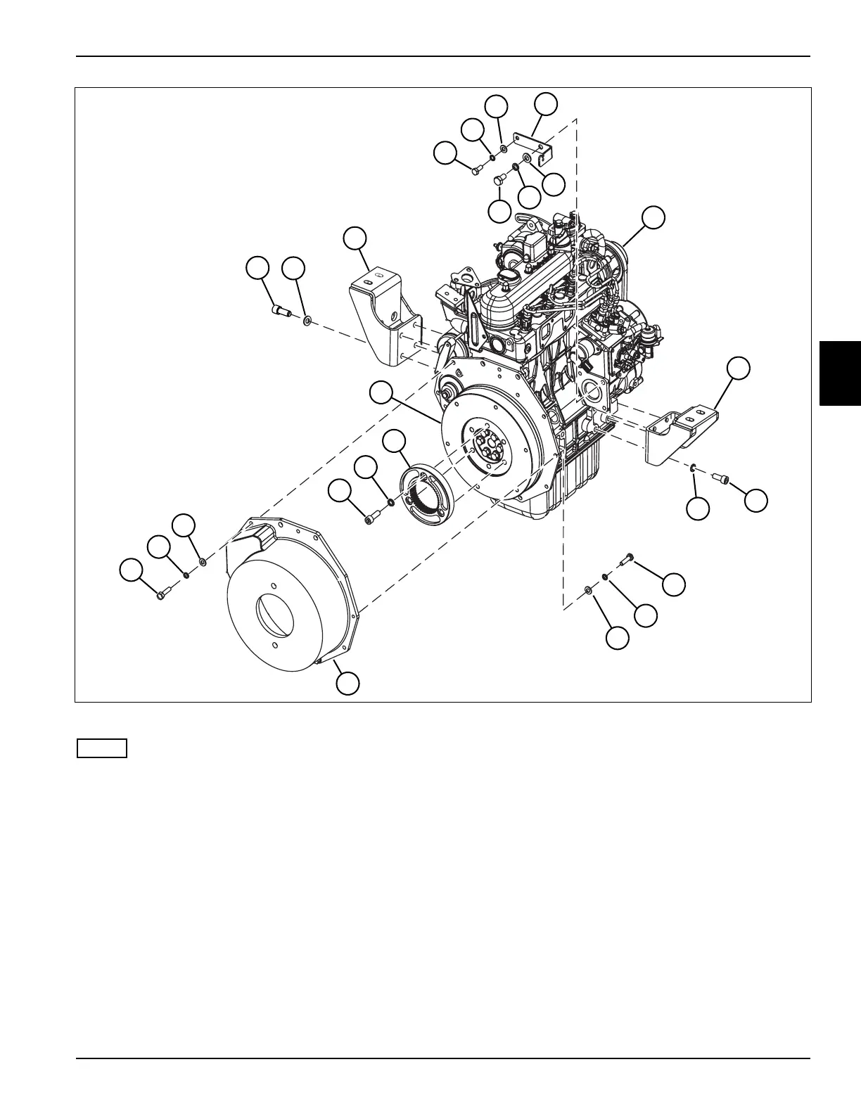
Figure 3-42
NOTE
Perform steps 26 through 32 if the engine is to be
serviced or replaced.
26. Remove two hex-head screws (65), lock washers
(66), and flat washers (67).
27. Remove five socket-head screws (69), lock washers
(70), and flat washers (71), and remove the bell
housing (69) from engine (61).
28. Remove three socket-head screws (72) and lock
washers (73), and remove Nylon flange (74) from the
flywheel (75).
29. Remove four screws (63) and lock washers (64), and
remove left engine mount (52) from engine (61).
30. Remove four screws (51) and lock washers (52), and
remove right engine mount (53) from engine (61).
31. Remove screw (54), lock washer (55), and flat
washer (56).
32. Remove screw (58), lock washer (59), and flat
washer (60), and remove throttle cable bracket (57).
Installation Notes
• Install the engine by reversing the order of removal.
• If replacing socket-head screws (72), they must be
replaced with the same size and grade as removed.
• Tighten socket-head screws (72) to 55 lb-ft (75 N·m).
TN1206
51
52
53
54
55
56
57
58
59
60
61
62
63
64
65
66
67
68
72
73
74
75
69
70
71