Do you have a question about the Jain Technology XONIC 100L and is the answer not in the manual?
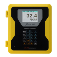
Provides an overview of the Xonic 100L flowmeter and manual.
Outlines electrical and electronic safety rules for installation and operation.
Lists the sequential steps required for installing the flowmeter and transducers.
Details the technical specifications of the Xonic 100L flowmeter and its components.
Allows users to set a password for preventing unauthorized access to the flow computer.
Used to identify flowmeters for remote communication and initial setup.
Enables selection between single or dual channel measurement modes.
Configures the transducer type, choosing between clamp-on, flowtube, or insert types.
Guides users to select the appropriate channel (1 or 2) for setup in single or dual channel modes.
Allows selection of pipe unit measurement between Metric (mm) and US units (inch).
Enables selection of the pipe material from a provided list for accurate measurement.
Indicates that Sonic Velocity for the pipe material is N/A for input.
Input field for specifying the pipe's inner diameter in millimeters.
Input field for specifying the pipe wall thickness in millimeters.
Option to select the lining material if the pipe is lined.
Indicates that Sonic Velocity for lining material is N/A.
Input field for specifying the lining thickness in millimeters.
Selects the type of liquid for which the flowmeter is being calibrated.
Displays the sound speed of the selected liquid automatically.
Indicates that minimum sonic velocity is N/A for input.
Indicates that maximum sonic velocity is N/A for input.
Flowmeter automatically displays the viscosity of the selected liquid.
Flowmeter automatically displays the density of the selected liquid.
Guides selection of the correct transducer type (B, C, D, E, F series) based on pipe requirements.
The flowmeter automatically selects the sampling clock, requiring no user input.
Selects the transducer mounting method, typically 'CLAMP-ON V' for most applications.
Specifies finding an installation location with sufficient straight pipe runs (10D upstream, 5D downstream).
Measure and input the calculated distance between transducers on the pipe.
Instructions to remove coatings and clean the pipe surface for optimal ultrasonic coupling.
Step-by-step guide for installing the mounting track onto the pipe using straps.
Instructions for applying couplant gel and mounting transducers onto the track.
Displays details of pipe and sensor configuration for verification.
Enables automatic installation procedure using patented AR mode for optimal signal detection.
Calibrates the flow reading to zero when the flow is stopped, ensuring accuracy.
Setting upper and lower flow limits to define operational boundaries.
Disregards very small flow values that are considered meaningless for specific pipe sizes.
Sets the time period over which the displayed flow is averaged.
Configures settings for total flow, including positive and negative totalization.
Configures high and low flow alarms to alert users of abnormal conditions.
Allows calibration of the flowmeter using calibration instruments for enhanced accuracy.
Manages signal gain automatically for optimal performance.
Adjusts the signal damping to smooth out fluctuations in readings.
Enables or disables a specific fixed setting, likely related to signal processing.
Selects the unit of measurement for flow volume (e.g., m³, Liter, Gallons).
Selects the unit of measurement for time (e.g., Second, Minute, Hour, Day).
Configures the number of decimal places for flow readings.
Option to use KILO for handling large flow values.
Selects the unit of measurement for totalized flow volume.
Configures the number of decimal places for totalized flow readings.
Option to use KILO for handling large totalized flow values.
Configures pulse output for batch total measurements.
Sets the mode for totalizing flow, including net, positive, or negative totalization.
Configures 4-20mA analog outputs for flow or velocity, including span settings.
Assigns relay functions for totalizer events like batch total, high flow, or low flow.
Configures analog inputs for external sensors like pressure or temperature.
Configures the second analog input for external sensors like pressure or temperature.
Sets the correct date and time for accurate data logging.
Configures communication settings like Baud Rate, Data Bits, Parity, Stop Bits, and Line Feed.
Assigns a unique ID to the flowmeter for network identification.
Sets the header text and data format for logged data.
Defines the character used to separate data fields in log files (Space, Comma, Tab).
Sets the time period between data logging intervals.
Synchronizes the logging time with an external source.
Enables or disables the data logging function.
Selects the communication mode (Normal, Jain View, CDMA, Modbus) and interface (RS232, RS485).
Displays current communication status and settings.
Displays records of the first and last logs, including date and output status.
Manages memory settings including log interval, time sync, and enabling logging.
Selects the port (RS232 or Firmware) for connecting to a laptop to download data.
Allows clearing of all stored memory data.
Manages external memory, log output, and log information.
Controls the capture and download of signal wave data.
Displays frequency division values related to signal reception.
Shows the distance from the impulse signal to the receive signal.
Indicates the number of pulses detected, with a default value of 5.
Displays the amplitude level of the signal, automatically set by the flowmeter.
Matches flow output with a remote indicator, setting 4mA for 0 flow and 20mA for max flow.
| Brand | Jain Technology |
|---|---|
| Model | XONIC 100L |
| Category | Measuring Instruments |
| Language | English |