31
UMG 511
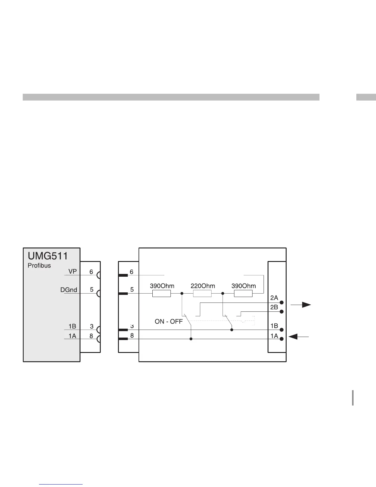
Connection of bus cables
The incoming bus cable is connected to
clamps 1A and 1B. The bus cable for the next
device in the line is connected to clamps 2A
and 2B. If no device follows in the line, the
bus cable must be terminated with resistors
(switch to ON).
In the ON switch position, the clamps 2A and
2B are switched off for the continuing bus ca-
ble.
Fig. profibus plug with terminal resistors.
Profibus- (Modbus)-Stecker (extern)
D-sub,
9 pin,
socket
D-sub,
9 pin,
connec-
tor
Profibus (Modbus) connector (external)
Terminating resistors
Other
profibus
stations
Screw-type terminals

 Loading...